Stavros’ notes
Welcome to my notes.
This site is autogenerated from a bunch of Joplin notes. I wrote a small script to read the notes, export them, and generate a static site. If you want to use the script and generate such a site for yourself, feel free to fork my repository:
https://github.com/skorokithakis/stavros-notes/
Just run ./joplinexport on your computer, it will read the database and create a site like this one and upload it to GitLab pages. Also, the build and move_html_to_dir scripts might be of interest.
Otherwise, enjoy my notes!
Last updated on April 12, 2025. For any questions/feedback, email me at hi@stavros.io.
Contents
Click on a link in the list below to go to that page:
- Bedtime
- MSM8916 LTE stick Linux port
- Macropad build
- Middle pendant firmware bring-up
- Sleight of hand
Bedtime
Project: AliExpress clock clone flashed with ESPHome to display Zigbee2MQTT sensor values.
Details
- ESP8266 inside, no broken-out GPIO pins
- Has TTL chip, visible when plugged into USB
- Flashed via USB, ESPHome config from reference video worked immediately
- Now displaying values from custom Zigbee2MQTT sensors
Resources
- AliExpress clock - Clone/lookalike version (not GeekMagic branded, saved $4)
- Reference video
Log
- 2024-12-26: Purchased clock from AliExpress. Opened it up, found ESP8266 inside.
- 2024-12-26: Flashed with ESPHome via USB. Config from reference video worked immediately.
- 2024-12-26: Customised display to show Zigbee2MQTT sensor values. Done and working.
Last updated on February 23, 2026. For any questions/feedback, email me at hi@stavros.io.
Macropad build
Project: Custom void16 redux macropad with nice!nano clone, ZMK firmware, and custom PCB.
Details
- Based on void16 redux
- nice!nano clone microcontroller, ZMK firmware, small battery
- PCB designed in KiCad, fabricated at JLCPCB
- Keycaps: red for layer buttons (top row, 4 keys), black for the rest (12 keys) - printed from flat MX keycap model
- 15 layers via button combinations: single buttons for layers 0-3, multiple simultaneous buttons for layers 4-14
- Modifier: Right Ctrl+Shift+Super (switched from left ctrl to avoid shortcut conflicts, removed Alt to avoid triggering language switch)
- Gaming layer (layer 12, buttons 0+2+3): WASD layout, ESC/TAB/CTRL on left column, ALT/Enter/Space on bottom row
- Combo to clear Bluetooth pairings: long-press all 4 layer buttons
PCB pin mapping
- Row 0: P0.02, Row 1: P1.15, Row 2: P0.10, Row 3: P1.11
- Col 0: P1.13, Col 1: P0.09, Col 2: P0.24, Col 3: P1.06
- Diode direction: col2row
- Footprint issue: one pin didn’t exist on nice!nano (wrong KiCad footprint), hand-wired to P1.06
- Silkscreen error: +/- labels for battery connector are reversed
Flashing
- Flash bootloader onto fake nice!nano boards using adafruit-nrfutil via USB-C (troubleshooting guide)
- Enter USB mass storage mode for firmware flashing: double-tap the reset pin quickly
Resources
- void16 redux
- Macro pad guide (jweather)
- Making a macro pad from scratch (MakerLuis)
- Video reference
- KiCad footprints: nice-nano, ProMicro, TheOneProMicro, key-switches.pretty
Log
- 2025-12-30: Project started. Printed void16 redux case and red keycaps. Hand-wired and soldered the build with nice!nano clone, ZMK, and small battery. It works!
- 2025-12-30: Connection stability issue - macropad disconnects/reconnects every few minutes while charging with Bluetooth headphones also connected. Investigating.
- 2025-12-30: Changed keymap from F13-F24 to regular keys with Ctrl+Shift+Super modifier. F-keys were triggering system actions (e.g. Alt+F20 mutes mic in GNOME). Added combo to clear Bluetooth pairings.
- 2025-12-31: Switched from left control to right control for modifier combo to avoid conflicts with left-ctrl shortcuts.
- 2025-12-31: Expanded from 4 layers to 15 layers using button combinations. Added gaming layer (layer 12) with WASD layout.
- 2025-12-31: Printing new keycaps - red for layer buttons, black for the rest.
- 2026-01-04: Designed PCB in KiCad and sent to JLCPCB for fabrication.
- 2026-01-21: PCBs arrived. Found footprint mistake - had to hand-wire one pin to P1.06. Also found silkscreen +/- reversal on battery connector.
- 2026-01-21: Flashed bootloader onto fake nice!nano boards. Updated ZMK overlay with correct GPIO pins for PCB version.
- 2026-01-21: 3D printed case refinements.
Last updated on February 23, 2026. For any questions/feedback, email me at hi@stavros.io.
Middle pendant firmware bring-up
Project: Voice recorder pendant - ESP32-S3 wearable with BLE sync, MP3 recording, and GPT-4o transcription.
Details
- ESP32-S3 SuperMini
- PlatformIO project, target: esp32-s3-devkitc-1
- Button pin: GPIO12
- BLE sync protocol with Python client
- BLE stream chunk size: 20 bytes (matching observed MTU 23)
- Records MP3, syncs via BLE, transcribes with GPT-4o to .txt files
- BLE advertising starts after successful recording and on boot when pending files exist
- ESP32-S3 ADC pins: ADC1 (GPIO 1-10) works with WiFi active, ADC2 (GPIO 11-20) not available when WiFi is in use. 20 channels total, 12-bit resolution (0-4095, 0-3.3V). S3 has better hardware calibration than old ESP32 - stick to ADC1 if using WiFi.
Log
- 2026-02-15: Initialized PlatformIO project for ESP32-S3. Implemented initial firmware and BLE sync protocol scaffolding. Added Python sync client with BLE transfer flow.
- 2026-02-15: Resolved board mismatch by switching to esp32-s3-devkitc-1 with USB mode adjustments. Ran staged firmware restore to isolate issues.
- 2026-02-15: Confirmed button pin as GPIO12. Switched BLE chunk size to 20 bytes for MTU 23 compatibility.
- 2026-02-15: Added ACK/SYNC handling hardening. Updated sync client to save MP3 and added GPT-4o transcription.
- 2026-02-15: Updated firmware so BLE advertising starts after recording and on boot with pending files. Fixed repeated file transfer behavior with delete-path normalization.
- 2026-02-18: Made a 3D printed case for the pendant - should be usable now.
- 2026-02-22: Installed a new digital microphone on the pendant.
Last updated on February 23, 2026. For any questions/feedback, email me at hi@stavros.io.
MSM8916 LTE stick Linux port
Project: Running Linux on a cheap MSM8916-based 4G LTE dongle using the OpenStick project.
Details
- Chip: Qualcomm MSM8916, 4x 1.0 GHz Cortex-A53
- RAM: 512MB, Storage: 4GB or 8GB eMMC
- Features: WiFi, GPS, LTE modem, Bluetooth (hardware-dependent)
- Frequency bands: 4G FDD LTE B1/3/5, 3G WCDMA B1
- Size: ~95x33mm, transmission rate: 150Mbps
- Ships with Android 4.4.4, reflashable to mainline Linux
- Common variants: UZ801 V3.0/V3.2, UFI001B/C, UFI003, UFI103S, UF896, SP970
- Default management IPs: 192.168.43.1:8080 (white) or 192.168.100.1 (black)
Flashing notes
- Enter EDL mode:
adb reboot edlor short EDL testpoint whilst inserting USB - UZ801 V3.0: Enable ADB at http://192.168.100.1/usb_debug.html
- UZ801 V3.2: Enable ADB at http://192.168.100.1/usbdebug.html
- UART voltage: 1.8V for UZ801, 3.3V for UFI models
- Backup eMMC before flashing (using bkerler/EDL tool)
- May need to replace firmware files in /lib/firmware for modem to work properly
Resources
- AliExpress listing
- OpenStick GitHub
- OpenStick Wiki
- PostmarketOS wiki - Detailed technical info
- Wim van ’t Hoog’s guide - Comprehensive guide with Debian Bookworm build, USB Gadget examples, pentesting applications
- HN discussion
Log
- 2025-12-27: Purchased MSM8916-based LTE stick from AliExpress.
- 2025-12-27: Researched OpenStick project, PostmarketOS wiki, and Wim van ’t Hoog’s guide.
- 2025-12-27: Backed up eMMC via EDL, flashed Linux firmware. Flash successful - Linux booting on the stick!
Last updated on February 23, 2026. For any questions/feedback, email me at hi@stavros.io.
Sleight of hand
Project: ESP32-driven analog wall clock - replace the timing IC and drive the coil directly from GPIO, enabling custom movement modes.
Repo: https://github.com/skorokithakis/sleight-of-hand
Details
- ESP32-C3 SuperMini (esp32-c3-devkitm-1 board definition)
- Cheap no-name sweeping quartz wall clock with timing IC removed
- GPIO 4 → Coil pin A, GPIO 5 → Coil pin B
- Coil resistance: 600 ohm
- 820 ohm series resistor on one coil pin (delivers 2.32 mA at 3.3V)
- 960 pulses per revolution (measured: 5761 pulses over 6 revolutions = 960.17)
- Original IC drives at ~62.5ms per cycle (31.25ms pulse + 31.25ms pause)
- WiFi AP name: SleightOfHand
- Three movements purchased total: two sweeping, one ticking
Key discovery: it’s a sweeping clock
- This is a sweeping-motion clock, not a ticking clock. The original IC drives continuous sweeping pulses (~30ms pulse, ~30ms pause), not one-pulse-per-second.
- All initial debugging failures were because the firmware was driving one pulse per second (ticking mode), which is the wrong drive mode entirely.
- Confirmed by buying a second identical clock, testing with battery first, and analyzing the original PCB with multimeter and oscilloscope.
Motor drive
- ESP32-C3 GPIO default drive strength is 40mA, much more than needed. Can reduce with
gpio_set_drive_capability()(5/10/20/40mA). UsingGPIO_DRIVE_CAP_0. - Tested timing limits: pulses down to 15ms (pulse and pause) work reliably. 10ms and below fail.
- Firmware uses 960-pulse model anchored to NTP minute boundaries. Two modes: steady (62ms cycle) and rush_wait (50ms cycle, ~12s idle at end of minute).
Power delivery
- Original battery: 1.5V across 600 ohm = 2.5 mA, 3.75 mW
- At 3.3V with no series resistor: only ~5.5 mA
- To match original 2.5 mA at 3.3V: need 1320 ohm total → 680-750 ohm series resistor
- Final: 820 ohm series resistor → 2.32 mA, slightly under original but works perfectly
Ticking movement
- Experimenting with a 150 Ω series resistor to lower tick strength
- Still tuning the resistor value
Communication
- MQTT control commands: stop, start, start_at_minute (waits for NTP minute boundary)
- MQTT reconnect only attempted during idle gap between revolutions to avoid stalling pulses
- UDP broadcast logging on port 37243 for wireless debugging (
nc -kul 37243)
Build notes
- Serial output on SuperMini requires USB CDC flags:
-DARDUINO_USB_MODE=1 -DARDUINO_USB_CDC_ON_BOOT=1 - Original driver PCB was desoldered and removed
- Idle state between pulses: high-impedance (
pinMode(..., INPUT))
Log
- 2026-02-10: Project initialized with PlatformIO (ESP32 Arduino framework). Basic coil driver written, repo created on GitHub. Switched board to ESP32-C3 SuperMini.
- 2026-02-11: Switched coil pins to GPIO 4 and 5. Removed series resistors. Extensive debugging - rotor flails/oscillates instead of making clean steps. Tested pulse widths 5-200ms, various drive strengths, both polarities. Tried short-brake after drive pulse. Measured coil at 600 ohm.
- 2026-02-12: Bought a second identical clock and tested with battery first - discovered it’s a sweeping clock, not ticking. Retrieved original PCB from trash, confirmed sweeping drive on oscilloscope.
- 2026-02-12: Updated firmware to 30ms pulse / 30ms pause continuous drive. Installed 820 ohm series resistor. Clock works perfectly.
- 2026-02-12: Measured 960 pulses/revolution. Rewrote firmware to NTP-anchored 960-pulse model with steady and rush_wait modes.
- 2026-02-12: Added MQTT control and UDP broadcast logging. Done and working.
- 2026-02-23: Working on adding ticking movement support. Debugging an off-by-one error in the ticking timing code - hard to pin down.
- 2026-02-24: Experimenting with a 150 Ω series resistor to reduce tick strength on the ticking movement. Still tuning.
Last updated on February 24, 2026. For any questions/feedback, email me at hi@stavros.io.
Contents
Click on a link in the list below to go to that page:
- A simple guide to PID control
- E6000 hinges
- FPV frequency chart
- Fixing the Matek ELRS receivers
- Getting uninverted SBUS on a no-name FrSky-compatible receiver
- Getting uninverted SBUS/SmartPort on the FrSky XSR receiver
- INAV tuning tips
- Miscellaneous
- Omnibus F4 V3 pinout
- Omnibus F4 pro servo diode
- QGroundControl to Mission Planner conversion script
- Transmitter external module pinout
- Transportable C1 Chaser
A simple guide to PID control
I made some changes to my quadcopter the other day for a new photography project I’m working on. Unfortunately, it turned out that it wasn’t good enough, and that I’d have to tune my PID loop, which I knew nothing about. After watching a few videos and reading a few things, I learnt enough to be dangerous, and to hopefully be able to explain the concepts simply, so I want to write them down here before I forget.
Basically, a PID loop can be thought of very simply as an equation that takes your current state as input and gives you what you need to do to reach a desired state as output. For example, if you had a radiator and wanted to heat a room, the PID loop would take the current temperature as input and tell you how high you needed to set the radiator on a 0-100% scale to achieve a desired temperature.
The PID loop has three components, and to tune it you need to set three weights that you multiply each parameter with.
That means that it’s basically output = P*prop, + I*intgr + D*deriv, where the terms are explained below:
P- proportional: This is the weight of the difference between the current position and the desired position. What this says about the radiator is “we’re still far away, we need more heat!”, so the more P you set, the higher the radiator will be set for a given temperature difference.D- derivative: BecausePis purely based on the difference between the current and target temperatures, it doesn’t know anything about inertia. So, even though your radiator will be getting closer to the target temperature, even when it’s very close, P will be saying “more heat, we’re not there yet!”, and cause you to overshoot your target, having to then go back (possibly turning the AC on, undershooting downwards, and then back upwards, oscillating like that for a long time). D helps by saying “whoa, we’re getting there, slow down with the heat”, and reducing the amount of heat you apply proportionally to how fast you’re getting to your target temperature.I- integral:Ihelps in the case where you left a window open in the room, andPis saying “okay we’re pretty close so set the radiator to 10% just for that final push”, but the room is leaking so that 10% will never get you to your target temperature.Ihelps by saying “Okay we’ve been trying but it’s not working, we’re still far, so we actually need a bit more heat than 10%”, by looking at the constant temperature difference you’ve been having lately, despite your best efforts. Basically,Ideals with accumulated error when you think you’re getting closer but all you’re doing is fighting losses, soIallows you to close that gap.
That’s pretty much it!
Last updated on January 07, 2021. For any questions/feedback, email me at hi@stavros.io.
E6000 hinges
I love Goop/E6000 glue, it’s very versatile and makes for a great bond. However, do remember to work with it outside, as it is not safe to breathe. One of the coolest things you can do with it is make hinges, for control surfaces as well as for any hatches you may have.
E6000 hinges are very strong (I tried tearing one by hand but couldn’t, in the end I had to cut it), and very flexible (you can easily turn the hinged surface 180 degrees up or down with very little force). They also have almost zero play, making them ideal for control surfaces.
Here’s how:
- Make sure your surfaces are clean and straight. Since you’re going to make a hinge by placing a very thin layer of glue over the two pieces, the pieces need to actually be straight and contacting on the part where the glue is going to go. If there’s a recess or groove where your elevons meet, this won’t work very well because your glue layer will be too thick to bend properly.
- Apply some masking tape parallel to the hinge line, 1 cm above and 1cm below it, so you don’t get glue elsewhere on the wing.
- Place the elevon/aileron/other control surface in position and apply some masking tape to the two ends, to hold the elevon in place. Take care to position it straight on both axes, the control surface should be at the same level as the wing surface across its length and the control surface shouldn’t be deflected up or down.
- Apply a thin layer of glue (around 1mm thin) on the top of the joint (not on both sides), and spread it evenly with a credit card or piece of paper.
- Wait for it to dry, and you’re done!
Because a description might be hard to follow, you can see the process in more detail in this video.
Last updated on March 22, 2021. For any questions/feedback, email me at hi@stavros.io.
Fixing the Matek ELRS receivers
The Matek ELRS receivers (ELRS-R24-D, ELRS-R24-S, etc) are dangerously close to out of spec, due to the addition of two XTAL capacitors. The Semtech chip Matek is using for the receiver already contains XTAL capacitors in it, so the two added capacitors are redundant and push the frequency close to the edge of the spec. This means that temperature changes might push the frequency off-spec, and cause a failsafe randomly in mid-air.
The Matek receivers with a silver boot button are more prone to the issue, but it’s also present in newer batches with gold boot buttons.
Luckily, this issue is easy to fix (and the fix is the same for both batches). You just need to desolder/remove the two capacitors shown below:
Last updated on December 04, 2022. For any questions/feedback, email me at hi@stavros.io.
FPV frequency chart
If you’re curious about which frequencies to use for video when there are multiple people flying FPV, as well as which bands are used by various manufacturers, here’s a handy chart:

It was made by 5zero7 RC with information from a Propwashed article.
Best channel groups
Here are the best channel groups for each number of pilots, from the chart:
- 2 pilots - E2 (5685), E6 (5905)
- 3 pilots - E2 (5685), F4 (5800), E6(5905)
- 4 pilots - E2 (5685), F2 (5760), F7 (5860) E6 (5905)
- 5 pilots - E2 (5685), F2 (5760), F4 (5800), F7 (5860), E6 (5905)
- IMD5C - R1 (5658), R2 (5695), F2 (5760), F4 (5800), E5 (5885)
- 6 pilots - E2 (5685), F1 (5740), F3 (5780), F5 (5820), F7 (5860), E6 (5905)
- IMD6C - R1 (5658), R2 (5695), F2 (5760), F4 (5800), F8 (5880), R8 (5917)
Last updated on January 09, 2021. For any questions/feedback, email me at hi@stavros.io.
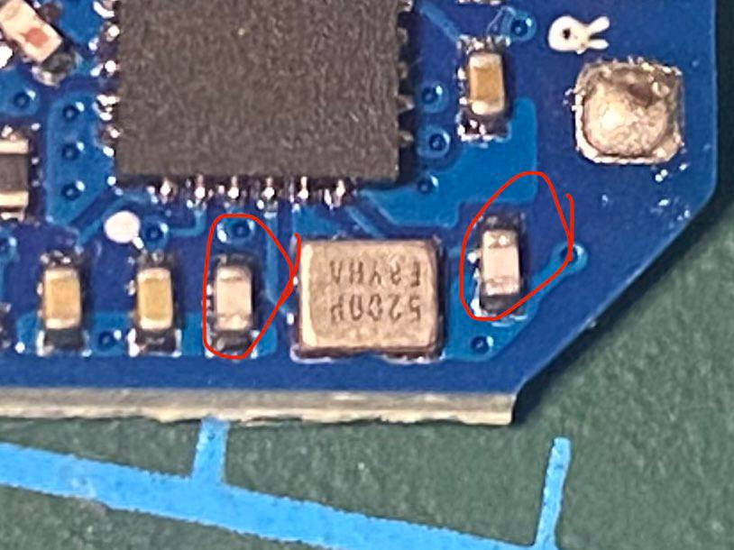
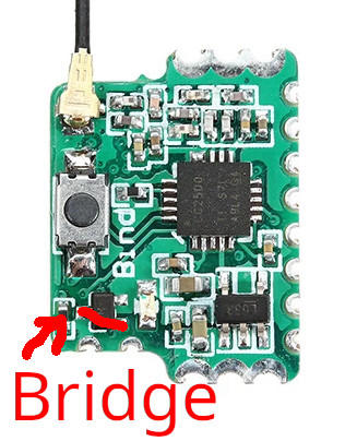
Getting uninverted SBUS on a no-name FrSky-compatible receiver
I got an RC receiver from Banggood.
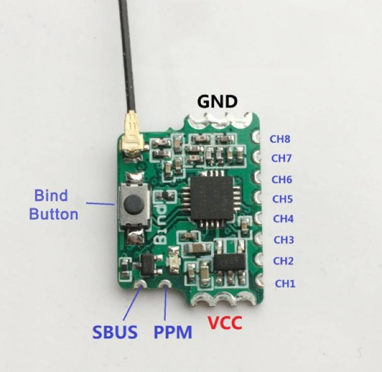
To bind, hold the button down while plugging in the power. When the LED is solid blue, you’ve bound.
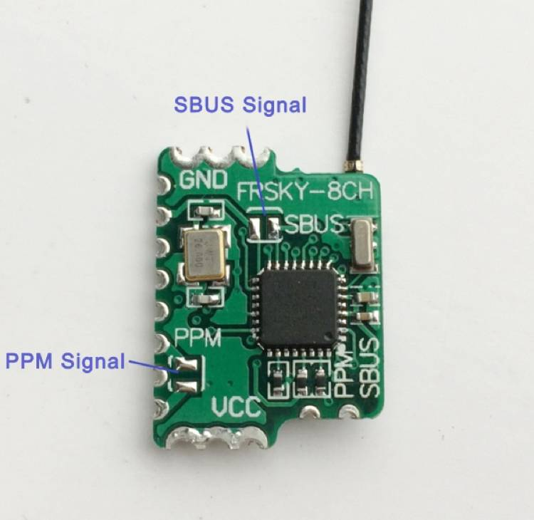
There’s uninverted SBUS on this pad:
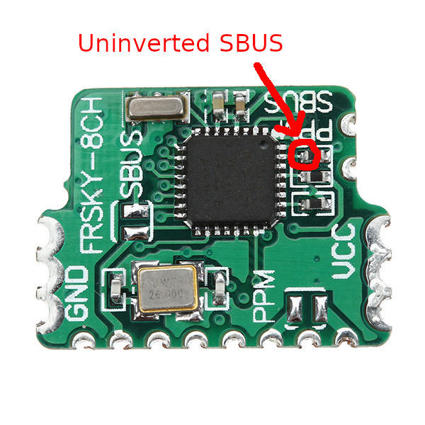
To break this out to the SBUS pad, I had to remove/bridge the resistor that is circled in the image, and remove/bridge the FET on the other side:
Last updated on February 07, 2026. For any questions/feedback, email me at hi@stavros.io.
Getting uninverted SBUS/SmartPort on the FrSky XSR receiver
To get uninverted SBUS/SmartPort on the FrSky XSR/X4RS receiver, you can repurpose the CPPM pad. Remove the two small resistors shown in the image, and solder the two lower pads (together) to either the CPPM pad or the MOSFET pin shown in the photo:
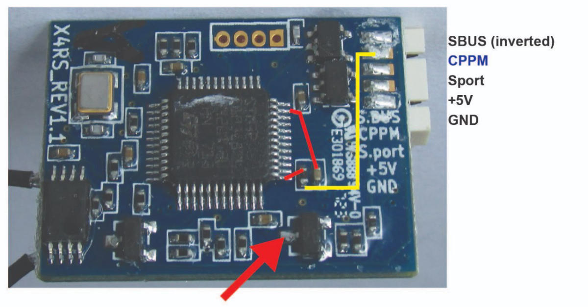
They should be soldered like this (remember to solder both resistor pads together):
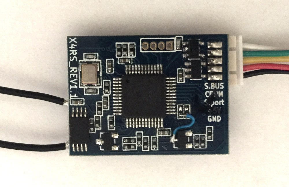
Now the CPPM pad will be uninverted SBUS/SmartPort instead. It seems to be a bit of a gamble whether you get SBUS or SmartPort, it might be firmware-dependent. On firmware 2.1.0 FPort, I actually got the uninverted FPort signal on the CPPM pin, which is what I wanted.
Last updated on November 24, 2020. For any questions/feedback, email me at hi@stavros.io.
INAV tuning tips
Here are some general INAV tuning tips and things I’ve learned throughout my builds. Keep in mind that these only apply to wings (and maybe planes), not quads:
- To make turns in automatic modes smoother, use
set nav_fw_control_smoothness = 8. - Pawel says that the idea of the software LPF is to replace the hardware LPF. Leave the hardware LPF set to 256 Hz and set the software LPF to 20-30 Hz, with a looptime of 1k.
Battery monitoring
To monitor how much battery you have left in flight, voltage isn’t a good indication because it can sag a lot. mAh is also not a good indication, because it doesn’t decrease linearly with voltage (when voltage drops, you need to consume more amps for the same amount of motor RPM, and thus thrust). Remaining energy (in Watt-hours) is a better way, using the “Wh drawn” INAV OSD item. In addition, INAV has heat loss compensation for the energy meter (done by simulating the internal resistance of the battery), which gives you a more accurate reading.
To calculate the Wh a battery can give, the best way is to charge or discharge it and see how many Wh were spent, if your charger shows you. Another way is to get a rough estimate using the formula no_cells * 3.7 * Ah. So, for a 1800 4S battery, the maximum Watt-hours are 4 * 3.7 * 1.8 = 26.64 Wh. You should not discharge more than 80% of that value, or you risk excessive wear to the battery.
For a 4S battery, I go with a rule of thumb: The maximum Wh is mAh / 85, so for a 5000 mAh battery I’ll land after 58 Wh consumed, which is around 80% of the battery consumed and gives a small margin for error.
More details can be found in the battery page in the INAV wiki.
(Thanks to Michel Pastor in the INAV Telegram group for this tip.)
Horizon drift issues
There’s a known problem with horizon drift on fixed wings. To ameliorate it, use set imu_acc_ignore_rate = 10. Setting this low is a good idea, but if it’s set too low then the accelerometer will effectively be ignored and the horizon will eventually drift. To reduce the accelerometer’s influence, you can also reduce imu_dcm_ki and/or imu_dcm_kp.
You can also try tuning fw_turn_assist_pitch_gain, although be careful to not set it too high because then the aircraft will stall trying to climb during a turn.
Adding a piece of black, porous foam (so wind can pass through) over the barometer has been known to help as well.
Last updated on January 01, 2021. For any questions/feedback, email me at hi@stavros.io.
Miscellaneous
This is a bunch of miscellaneous info that wouldn’t fit anywhere else:
- The ZOHD Dart 250g with the stock motor draws 4.5A on 2S with the 5x5 propeller. It draws the same amperage at exactly 75% throttle with a 3S battery and the same propeller.
- When wiring your electronics, make sure you don’t have any ground loops. This means that there should only be one ground wire going to each component. For example, the ESC has one ground wire for power (to the battery) and one for signal (to the FC), you should only use one of the two (the one going to the battery). What you can do for the other ground wire, though, is twist it around the signal wire and only connect it to the FC side, to reduce emissions. If you have coaxial cable, you can do the same, connect the outer shielding to the FC’s ground, and don’t connect the other side anywhere, and use the core as signal.
- If you want to embed knurled nuts in foam so you can use screws, use a soldering iron. Set the iron to 150 C, put the nut on the tip of the iron, and push the nut into the foam. It will slowly melt the foam and embed itself quite firmly. Don’t use a higher temperature or you’ll open a larger hole and the nut won’t fit snugly.
- This is the command I used to flash an ESP8285 M3 with esp-link:
esptool.py --port /dev/ttyUSB0 --baud 115200 write_flash -fs 1MB -fm dout \ 0x00000 boot_v1.7.bin 0x1000 user1.bin \ 0xFC000 esp_init_data_default.bin 0xFE000 blank.bin - Propellers have a direction: The top usually has letters like, for example, “6040” (which denotes the size and pitch of the propeller), and the top needs to always point towards where the plane will be flying (the front). No matter if you have a pusher or puller, the top of the propeller needs to be pointing forward.
- When it comes to cameras/standards, the difference between PAL and NTSC is that PAL has higher resolution (625 lines, ie 576i for PAL vs 525 lines, ie 480i for NTSC), but lower framerate (25 fps for PAL vs 29.97 fps for NTSC). I use PAL because I prefer having higher resolution.
- If doing manual/hand launches of planes/wings, you’ll notice that you need to have your hand on the pitch/roll stick when launching, which means you need to launch with your left hand, which is where the arm and throttle controls usually are. That makes it hard to throttle up to start the launch, or down (or disarm) in an emergency.
To make things a bit easier, I set the back right switch (SG) to override the throttle and set it to the launch throttle (40% for me, for example). That way, I can arm, keep the throttle down, and flip SG with my right hand. That will throttle up enough to easily launch the wing, and if something goes wrong I can still either disarm or flip SG down so the motor stops again. - ESCs that run on the DShot protocol don’t need throttle calibration, you can go ahead and use them right away and they’ll do the right thing.
Motor and prop stuff
Here are the things I know about motors and propellers:
- The larger and steeper the propeller, the harder it is for the motor to turn.
- The more KV the motor is, the faster it turns, and the harder it is for it to turn.
- The harder the motor has to turn, the more current it draws, and the hotter it gets.
- The larger the (physical) size of the motor, the more heat it can dissipate.
- The more amps (current) the motor draws, the hotter it gets (proportional to the square of the current).
- If the motor gets too hot, some part of it may melt. This ruins the motor.
- The smaller a propeller, the more quickly it can turn, and the more it can accelerate.
- The larger a propeller, the more efficient it is.
Recommended BLHeli ESC configuration for fixed wing
If you have a BLHeli/BLHeli32 ESC, these settings are recommended:
- Temperature protection: 90 C
- Motor timing: Auto
- Throttle cal enabled: Enabled
- Non-damped mode: Enabled
- Sine modulation mode: Enabled
- Brake on stop: 100%
Last updated on January 17, 2023. For any questions/feedback, email me at hi@stavros.io.
Omnibus F4 pro servo diode
To isolate the servo 5V rail from the controller’s 5V power supply, remove this diode:
Now the servos’ 5V rail can be powered from another 5V supply to avoid servo current backflow into the FC.
There’s also a schematic for this FC.
Last updated on April 09, 2021. For any questions/feedback, email me at hi@stavros.io.
Omnibus F4 V3 pinout
This is the pinout of the Omnibus F4 V3:

Also:
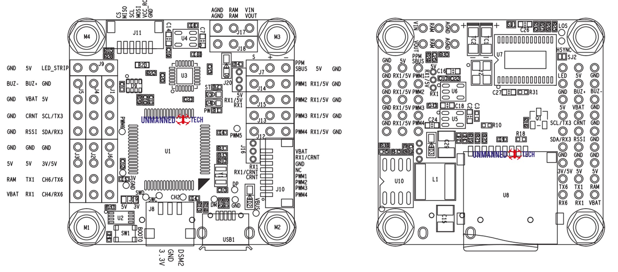
Last updated on January 06, 2021. For any questions/feedback, email me at hi@stavros.io.
QGroundControl to Mission Planner conversion script
If you have a parameter dump from QGroundControl, I wrote a small script that will convert it to a Mission Planner compatible file. You can also use Parachute to do your backups/restores/conversions.
Just save this script somewhere as convert_qgc_params and run it as ./convert_qgc_params @@M1@@ @@M2@@:
#!/usr/bin/env python3
import sys
from decimal import Decimal


def format_float(f):
    return "{0:f}".format(Decimal(f).quantize(Decimal("1.0000000")).normalize())


def main(infile, outfile):
    with open(infile) as ins:
        inputs = ins.read()

    lines = []
    for line in inputs.split("\n"):
        if not line or line.startswith("#"):
            continue
        vehicle_id, component_id, name, value, type = line.split("\t")
        v = value
        if type == "9":
            v = format_float(float(value))
        lines.append(f"{name},{v}\n")

    with open(outfile, "wt") as outs:
        outs.writelines(lines)


if __name__ == "__main__":
    main(sys.argv[1], sys.argv[2])
Last updated on March 04, 2021. For any questions/feedback, email me at hi@stavros.io.
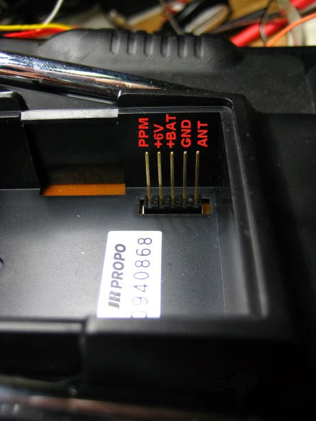
Transmitter external module pinout
The transmitter (Taranis, Jumper, RadioMaster, etc) pinout is, from top to bottom:
- PPM
- +6V
- +BAT
- GND
- ANT
It’s illustrated in this photo:
Last updated on November 24, 2020. For any questions/feedback, email me at hi@stavros.io.
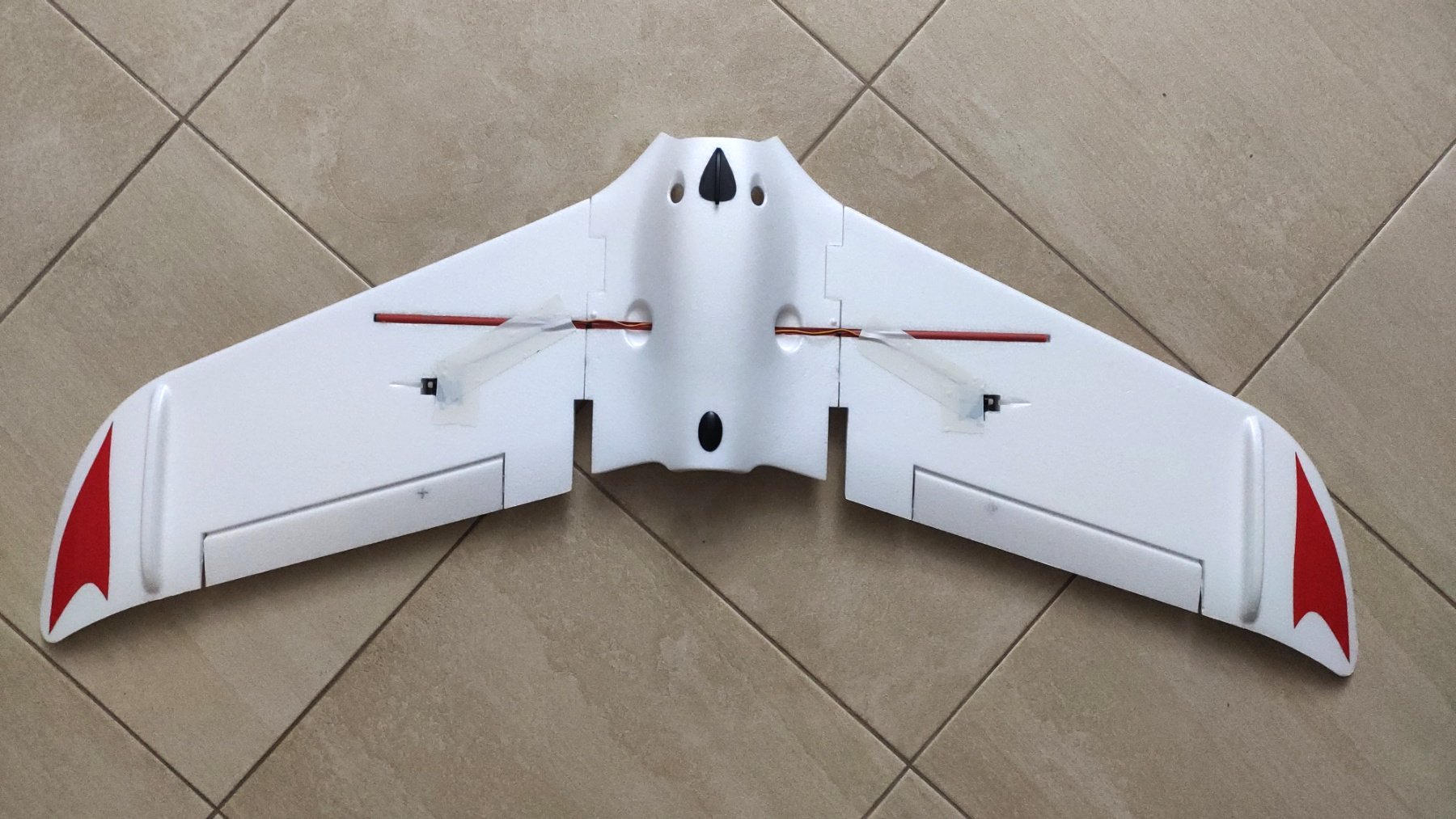
Transportable C1 Chaser
I have a C1 Chaser, and it’s a fantastic wing. It flies great, and is very efficient. The only problem I had with it was that it’s too long to easily carry around, as it has a 1.2m wingspan.
I thought that a C1 Chaser that can break apart for easy transport would be the ideal long-range wing, so I bought a second one and made some modifications to it. I’m listing the modifications here so you can do the same if you want to.
Spar
The biggest issue is making the spar removable. The best way I’ve found to do that is to use IKEA drinking straws, they have an internal diameter of around 7.5mm, making them ideal for putting the spar through. If you find the spar has too much jiggle, I’ve found that applying some CA glue around it makes it thick enough to fit snugly in the straw.
I’ve cut three straws to length, sanded the straws and the spar channel a little with coarse sandpaper, and glued the former in the latter, as you can see here (the straw in the photo is not cut to length yet):
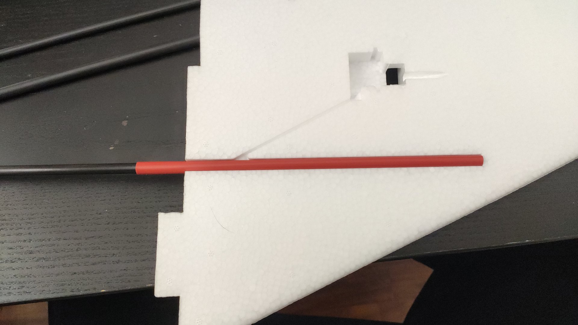
Make sure to leave a few mm from the inside edge of the wing (so the straw doesn’t touch the edge, again not pictured in the photo), so the spar’s edge doesn’t rub against the straw, to avoid splitting it. Also, leave the spar in the straws while gluing, so the straws don’t lose their shape (but make sure you don’t get glue on the spar and end up gluing it to the straw).
For glue, I use E6000 (sold as Goop in the US) for pretty much everything, but for this one you can use your favorite glue that you know won’t dissolve EPO.
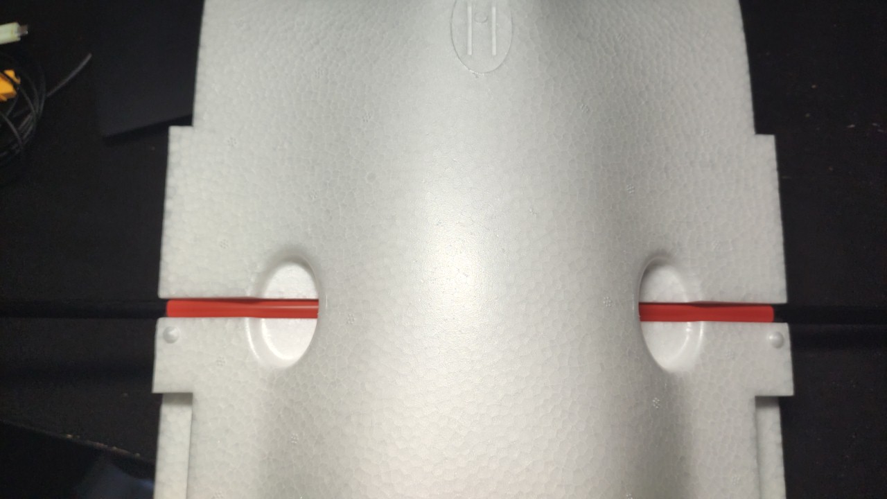
This is what the final result will look like:
Wings
Connecting the wings has two problems:
First, you need the wing to be stable against rotation around the spar. Already, the notch the C1 has stops the wing from rotating up, but it does not stop it from rotating down (since you’re meant to glue it in place).
Second, you obviously need the wing to be stable against left/right motion, or it will slide off the spar. To solve these problems, I designed a simple connector with two halves, one of which goes onto the fuselage and one onto the wing:
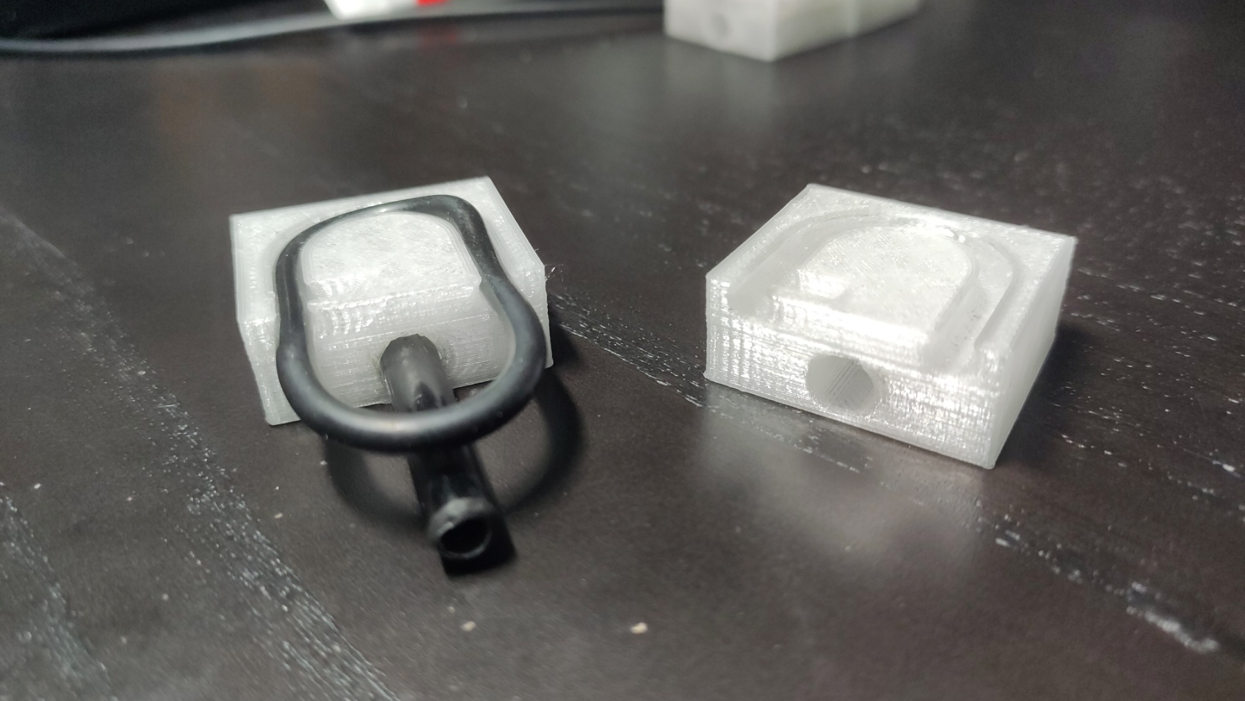
The connector has two components, one is a cylindrical channel for a carbon tube (which you can glue to one of the pieces, as in the photo) that stops the wing from rotating around the spar, and the other is a channel for an o-ring, which keeps the two halves from moving left to right.
I used a 6mm outer diameter carbon tube and an o-ring with an inner diameter of 28mm and a cross-section diameter of 3.5mm. A slightly thicker and slightly longer o-ring will also probably work.
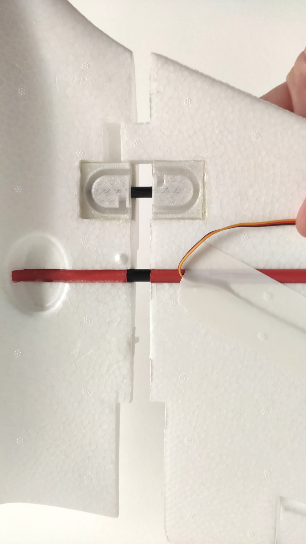
To install, place the connector over the underside of the wing and mark the outline, then cut the foam and glue the connector in. Do the same with the other side, into the fuselage, as shown in the photo below. To make sure the connectors are glued straight, I recommend cutting the foam to shape, placing the connectors in on both sides, and sliding them into each other (using the tube), making sure to leave some distance and watch for any places where glue has leaked, to prevent the wing and the fuselage from gluing together. Also, make sure to not use glue the part of the connector that’s not going to be next to foam, on the fuselage side, to prevent the wing tab from adhering when you slide them together (watch out for glue seeping from under the connector towards the tab).
This is the end result:
To mount the wings, just insert the spar into the fuselage, insert the wings (making sure both tubes go into their respective holes), and place the o-ring into both halves of the connector. That gives you a secure and quick assembly.
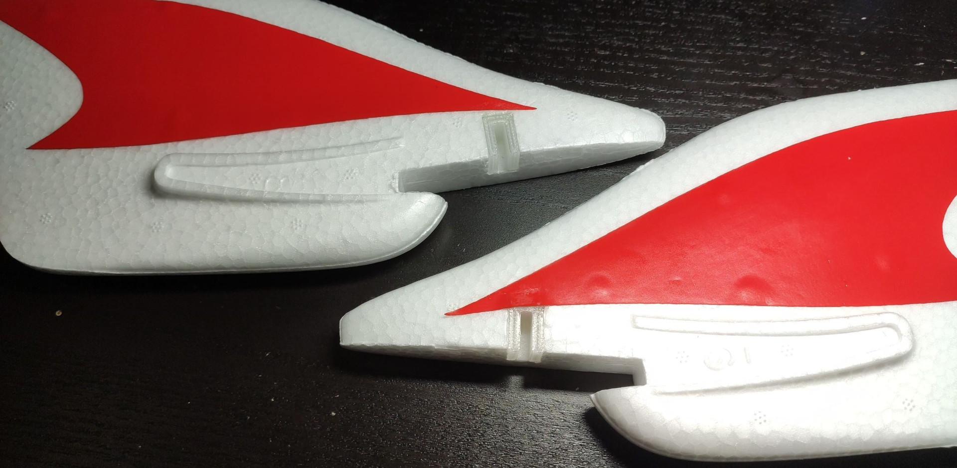
Vertical stabilizers
The last part is securing the vertical stabilizers. I did this with two very small 3D-printed pieces, I slot the stabilizers horizontally (on the left/right axis) onto the fuselage and then connect the wings, which keeps the stabilizers securely in place.
First, press the stabilizer-side part (the Π-shaped one) onto the stabilizer on the place where you want it (I put it as shown in the photo), and cut slightly inside the indentation it creates. Then, glue it into place:
Then, insert the fuselage-side part (the inverted-T-shaped one) into the stabilizer-side part, align the stabilizer with the fuselage and press it in, to create the indentation onto the fuselage EPO, so you know where to cut. Insert the part into the cut and glue it in:
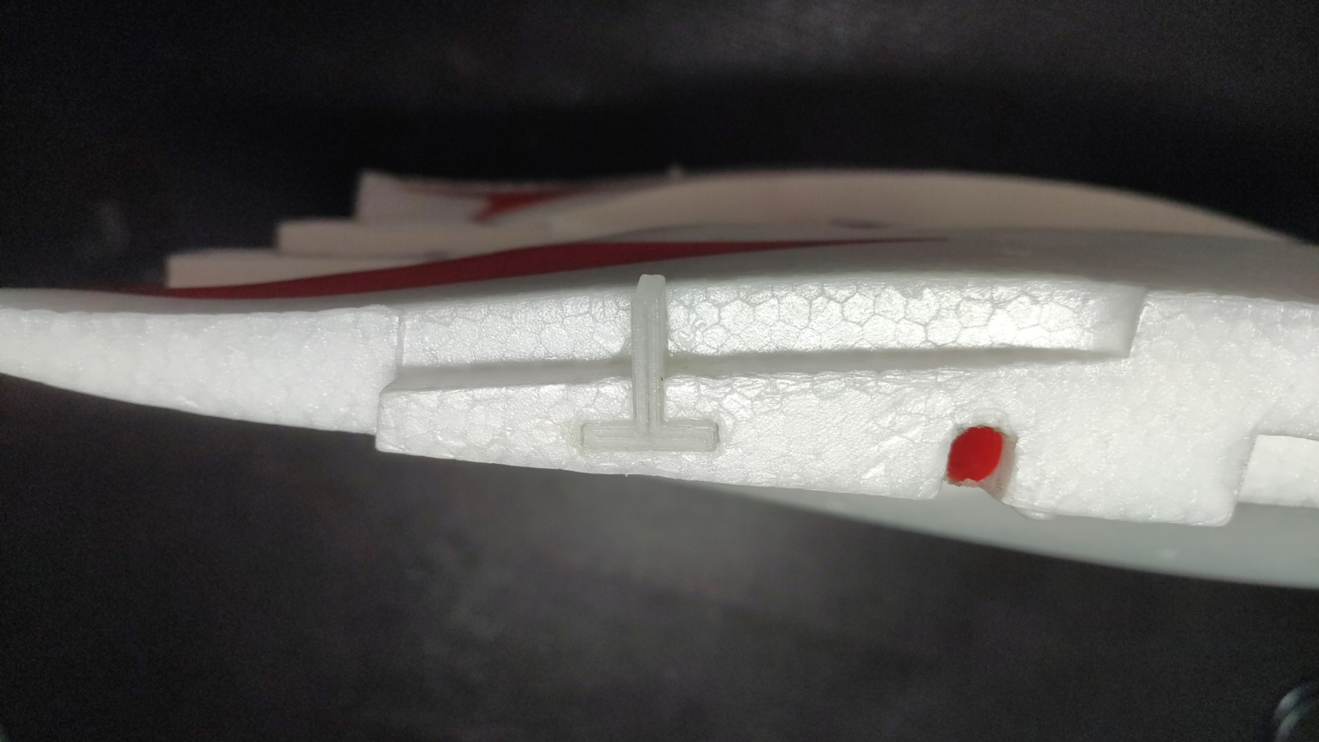
When everything has set, you can install the stabilizers by simply slotting the two parts into each other and mounting the wing. That way, the stabilizer isn’t going anywhere, and you can install and remove it very quickly.
The end
You’re done! Enjoy your disassemblable, transportable C1 Chaser!
Last updated on February 03, 2021. For any questions/feedback, email me at hi@stavros.io.
Contents
Click on a link in the list below to go to that page:
- ArduPilot recommended settings
- ArduPilot setup checklist
- Bitmask calculator
- Building ArduPilot
- Configuring a switch as a relay
- Current sensor calibrator
- DJI FPV configuration
- ELRS preferred configuration
- HD OSD tool
- Installing WTFOS on DJI
- Miscellaneous notes
- Reverse thrust
- Statistics calculator
- TECS tuning calculator
- Transfer config between craft
- Tuning the TECS
ArduPilot recommended settings
This section contains some recommended settings for ArduPilot. Nothing is set in stone, these are just some defaults I’ve found to work well.
GPS
GPS_GNSS_MODE=71  # Enable GPS/SBAS/Galileo/GLONASS.
GPS_RATE_MS=100   # 10 Hz update rate.
Crossfire/ELRS
SERIALn_PROTOCOL=23  # Crossfire/ELRS.
RC_OPTIONS=800       # 5 - Arming check throttle.
                     # 8 - CRSF telemetry passthrough.
                     # 9 - Suppress CRSF mode/rate message for ELRS.
Expo
30% expo is a good starting point:
MAN_EXPO_ROLL=30
MAN_EXPO_PITCH=30
MAN_EXPO_RUDDER=30
Miscellaneous
INS_GYRO_FILTER=60     # Faster gyro updates.
SCHED_LOOP_RATE=100    # Faster scheduler updates.
Servo update rate
If you want a higher servo update rate (because of digital servos), it is probably better to set the scheduler loop rate to the frequency you want, and enable ONESHOT on the servos:
SCHED_LOOP_RATE=200   # As above.
ONESHOT_MASK=6        # Change to whatever channels your servos are on.
Switch arming
If you want to use switch arming rather than stick arming, here are the relevant parameters:
RCx_OPTION=153
ARMING_RUDDER=0
Last updated on November 09, 2022. For any questions/feedback, email me at hi@stavros.io.
ArduPilot setup checklist
This is a short guide for setting up ArduPilot on a flying wing. I use an Omnibus F4 that was previously set up for INAV (so motor on 1, elevons on 3/4), so most of this guide will be geared to that. If you use a different controller, your mileage may vary.
You should keep the full list of ArduPilot parameters open, for your reference while tuning.
Helper utility
I have created a utility that lets you easily get/set/backup/restore parameters from the command line. It’s called Parachute, and you can download it here:
https://gitlab.com/stavros/parachute
Building ArduPilot
See Building ArduPilot for instructions on how to build the latest version.
Hardware setup
The values in this section are specific to the Omnibus F4, but the settings aren’t, so you’ll usually need to adjust your outputs to your specific configuration but you probably won’t need to skip many of the steps here.
- Connect GPS to UART 6 (SERIAL4). You don’t need to do anything else for GPS, it should work out of the box. If it doesn’t, set
SERIALn_PROTOCOL=5. - Change the FC’s orientation with
AHRS_ORIENTATIONand monitor the artificial horizon to see if it moves correctly. - Make sure the artificial horizon is level when the plane is level on the ground. Use the “calibrate level” button or
AHRS_TRIM_Yto correct it if it’s not. - Calibrate the accelerometer. “Forward” here needs to be the forward direction of the plane, not the arrow on the FC.
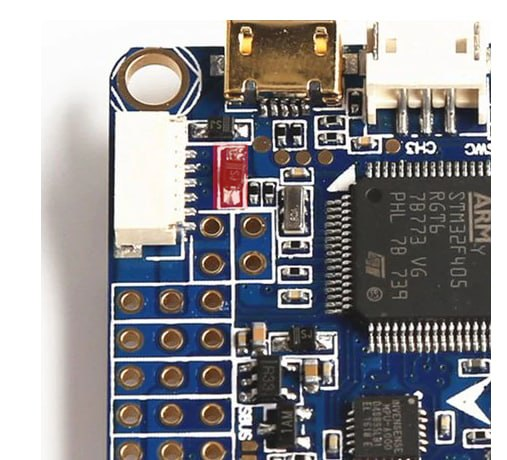
- Connect Fport to a UART. I chose UART 3 (SERIAL2). If you want to use UART 1, you should set the RC input jumper to PPM on the F4 to disconnect the SBUS inverter from the pin.
- To get Fport working with UART 3, you need to set
BRD_ALT_CONFIG=1, to get UART 3 to act like a UART instead of I2C on the Omnibus F4. - Set the following for Fport on UART 3:
SERIAL2_PROTOCOL=23 # RCIN SERIAL2_BAUD=115 SERIAL2_OPTIONS=4 RSSI_TYPE=3 - Once Fport works, reverse the elevator with
RC2_REVERSED=1. - Set up your servo functions and trims:
All these values are necessary, because usually theSERVO1_FUNCTION=70 # Throttle SERVO1_MIN=1000 SERVO1_MAX=2000 SERVO1_TRIM=1000 SERVO3_FUNCTION=77 # Left elevon SERVO3_MIN=1000 SERVO3_MAX=2000 SERVO3_TRIM=1500 SERVO4_FUNCTION=78 # Right elevon SERVO4_MIN=1000 SERVO4_MAX=2000 SERVO4_TRIM=1500SERVOn_TRIMwon’t be at 1500. - Switch to FBWA and validate that the control surfaces move correctly. If they don’t, set
SERVOn_REVERSED=1. It needs to be FBWA and not MANUAL because FBWA has some additional processing like PIDs, etc. - Set
SERVO_BLH_OTYPE=4for DShot150 andSERVO_BLH_MASK=1to enable it for the motor. - Set
COMPASS_ENABLE=0if you don’t have a compass, otherwise calibrate it (not detailed here). - Set
TERRAIN_ENABLE=0to get rid of the terrain warning. - Set the FC’s pitch relative to the body with
AHRS_TRIM_Yand check that FBWA mode flies level. - If you don’t use logging, set
LOG_BACKEND_TYPE=0. If you do use logging, setLOG_DISARMED=1 LOG_FILE_DSRMROT=0to prevent the EKF from diverging and causing problems on takeoff. - Check the preflight errors to warn on, though usually leaving it set to “all” is fine.
- Set up the OSD (Mission Planner has a very nice UI for that). Keep in mind that ArduPilot’s airspeed and windspeed estimation are quite good, so you may want to add those even if you don’t have an airspeed sensor. You may also want to set up multiple screens, I use a potentiometer to switch between the four different screens of the OSD:
- One with everything on (for debugging), which is also set as the
OSD_ARM_SCR/OSD_DSARM_SCR. - One with the artificial horizon, system messages and some basic info like RSSI, battery, ground speed and altitude.
- A minimal screen with just system messages and battery/RSSI/speed/altitude.
- A screen with just system messages, for when I want to enjoy the scenery.
- One with everything on (for debugging), which is also set as the
Radio-related
- Set your radio channels to AETR and run the radio calibration in the calibration section of ArduPilot.
- Add a killswitch to the radio that overrides the mode to manual and the throttle to 0. This way it’s really easy to kill the motor right away, but you still need to go through the arming procedure to get the motor running (thanks to Michel Pastor for this great idea).
- Set up modes, possibly having switches override the mode channel to the mode you want.
What I do is set a given channel as the mode channel, and make that channel always output -100% on the radio. Then, I set up channel overrides for each switch, keeping in mind that overrides in OpenTX are executed in order (so the bottom override has the highest priority).
That way, I set MANUAL/ACRO/FBWA to be lowest priority (on the same switch), then CRUISE to override those, then LOITER, RTL in that order. Finally, I add AUTO to a switch on its own channel.
Keep in mind that whatever mode you have on its own channel might be overridden if you flick a different switch.
Auto modes
- Set
SERVO_AUTO_TRIM=1so the aircraft trims itself while flying. - Set
FS_SHORT_ACTN/FS_SHORT_TIMEOUT/FS_LONG_ACTN/FS_LONG_TIMEOUT. I tend to disable the short action and set long to RTL. - Set
FLIGHT_OPTIONS+=16so the aircraft climbs first before starting to return to home. - Change
AUTOTUNE_LEVELaccording to how aggressive you want the tune. - Set
ACRO_PITCH_RATE/ACRO_ROLL_RATEaccording to your craft. - Set
THR_PASS_STAB=1so you have total throttle control in ACRO/FBWA/STABILIZE. - Set
ARSPD_FBW_MIN/ARSPD_FBW_MAXto the minimum and maximum airspeed you want auto modes to fly (see the TECS tuning guide below for details). - Set
MIN_GNDSPD_CM=833(30 km/h) so the craft makes an effort to return even under high winds. - Set
RTL_SINK_MAX=2to enable a very slow descent on RTL (you generally don’t need to descend fast on RTL).
Auto takeoff
- Change
TKOFF_THR_MAXto the desired max takeoff throttle. - Change
TKOFF_ALTto the altitude you want takeoff to reach. - Set
THR_SUPP_MAN=1so you can manually set the autolaunch “idle” throttle (before the throw). - Set
TKOFF_THR_MINACC=18for the takeoff throw to activate takeoff with a minimum of 2g. - Set
TKOFF_LVL_PITCHto your desired angle (20 is a good value). - Set
TKOFF_THR_DELAYto the number of deciseconds that you want the motor to wait before it starts up. - Set
FLIGHT_OPTIONS+=64so the aircraft doesn’t oscillate on auto takeoff without an airspeed sensor. - Potentially set
TKOFF_THR_SLEW=-1to make the throttle spin up faster.
Recommended settings.
See the recommended settings page for other recommended defaults.
In the field
- Run an autotune.
- Fly in FBWA and see if you’re gaining/losing altitude. Pitch up/down to fly level, check the pitch on the OSD, and use the formula
old_value+pitch*π/180to get the new value forAHRS_TRIM_Y(in radians). - After you set
AHRS_TRIM_Ycorrectly above, fly in FBWA at full throttle (or whatever throttle you feel is “full” enough, and note that value), and note the pitch you need so that the wing doesn’t climb or sink. Then, setKFF_THR2PTCHwith the formulapitch_value_in_deg * 100 / throttle_percentage.pitch_value_in_degshould be positive if you needed up pitch and negative if you needed down pitch.
(Many thanks to Michel Pastor and mfoos for their help with everything in this note.)
Last updated on April 15, 2023. For any questions/feedback, email me at hi@stavros.io.
Bitmask calculator
(Many thanks to mfoos for writing this note.)
Last updated on October 07, 2022. For any questions/feedback, email me at hi@stavros.io.
Building ArduPilot
Because building ArduPilot is a bit complicated, I’ve written a short script that uses Docker to build AP in a controlled environment.
Copy it from here, save it to a file called docker_build.sh in the root of the ArduPilot repo, and run it with docker_build.sh @@M1@@. Output files will be stored in build/@@M2@@/bin/, and you can flash them with the INAV configurator by putting your board in DFU mode and uploading the arduplane_with_bl.hex file.
Here’s the script:
#!/usr/bin/env bash

set -euox pipefail

if [ $# -ne 1 ]
  then
    echo "No board supplied, run as ./docker_build.sh <board name> or ./docker_build.sh list"
    exit 1
fi

BOARD=$1

cd "$(git rev-parse --show-toplevel)"

git submodule update --init --recursive

git checkout Dockerfile
echo "RUN pip install intelhex" >> Dockerfile
echo 'ENV PATH="/home/ardupilot/.local/bin:/usr/lib/ccache:/ardupilot/Tools/autotest:${PATH}"' >> Dockerfile
cat Dockerfile

docker build . -t ardupilot
git checkout Dockerfile

# We need to update the PATH with the location of the ARM EABI inside the Docker
# container, so we write a script that handles this and the actual building.
cat <<EOF > undocker_build_temp.sh
#!/usr/bin/env bash

set -euox pipefail

export ARM_EABI=/opt/\$(ls -1 /opt/ | grep gcc-arm-none-eabi)/bin/
export PATH=\$ARM_EABI:\$PATH

./waf configure --board="\$1"
./waf build
EOF

chmod +x ./undocker_build_temp.sh

docker run --rm -it -v "$(pwd)":/ardupilot ardupilot ./undocker_build_temp.sh "$BOARD"

rm undocker_build_temp.sh
Last updated on September 07, 2021. For any questions/feedback, email me at hi@stavros.io.
Configuring a switch as a relay
If you want to connect a relay of some sort (something that accepts a low/high signal, like a camera control) to a PWM output (the servo outputs), you need to do a few quick things. The actual numbers will vary depending on your FC, but here’s what worked for me with a Matek F405-Wing:
- Set the channel you want the relay to trigger on as a controller for the first relay (here I’ll assume you want to control the first relay on channel 11):
RC11_OPTION=28 - Set the pin number for the relay you want to control. This is a bit fuzzy, it depends on your flight controller, but try a few out. This is what worked for me, for S6 on my F405-Wing:
RELAY_PIN=55 - Set a servo to act as a GPIO output. I’m assuming here you want
SERVO6, though I’m not quite sure how the servo selection maps to theRELAY_PINselection above. For me,AUXOUT6andSERVO6worked:SERVO6_FUNCTION=-1
If you’re amazingly lucky, you should be all set. If not, you need to play with the 50 in the RELAY_PIN parameter and the 6 in the SERVO6_FUNCTION until something works.
Last updated on September 11, 2021. For any questions/feedback, email me at hi@stavros.io.
Current sensor calibrator
This calculator will allow you to calibrate your current sensor better than with the mAh charged vs mAh consumed method.
You need a current meter and a way to see what current and throttle percentage the FC reports (the OSD is a good way to do this).
The steps to follow are:
- Make sure you have capacitors on ESCs so the measurement will not be influenced by errors from ESC noise.
- Set
BATT_AMP_PERVLT=100andBATT_AMP_OFFSET=0. - Power your plane with propellers on and a current meter connected between FC and pack.
- Arm and run the motor in manual mode. For four different throttle positions, note down: The throttle position (from the OSD), the reported current (from the OSD), and the actual current (from the current meter). The best throttle positions to use would be 25%, 50%, 75% and 100%. Do not check current on idle as this will be inaccurate.
- Enter the values below, and the calculator will give you the proper BATT_AMP_PERVLT and BATT_AMP_OFFSET values that you now need to write to your plane’s parameters.
| OSD current: | |
| Real current: | |
|
Results: |
|
BATT_AMP_OFFSET:
|
|
BATT_AMP_PERVLT:
|
(Many thanks to mfoos for writing this note.)
Last updated on December 27, 2025. For any questions/feedback, email me at hi@stavros.io.
DJI FPV configuration
Configuring ArduPilot for DJI FPV
If you’re using the DJI FPV system, here’s the relevant configuration you need to set:
- Set
OSD_TYPE=3. - Set
SERIALn_PROTOCOL=33 SERIALn_BAUD=115 SERIALn_OPTIONS=0(DJI FPV). - Create a text file called
naco.txton the SD card of the Air Unit with the text1in it to unlock full power. - Create a text file called
naco_pwr.txton the SD card of the goggles with the textpwr_2in it to unlock more full power. - Set “Custom OSD” to “on” in the goggles menu.
- Arrange your OSD elements how you like them.
That’s it!
Configuring AP for the DJI O3
If you’re using DJI O3, this is what you need to do:
- Set ,
OSD_TYPE=5for MSP_DISPLAYPORT. - Set
SERIALn_PROTOCOL=42 SERIALn_BAUD=115 SERIALn_OPTIONS=0for DisplayPort. - Set
MSP_OPTIONS=5for telemetry mode and BTFL fonts. - Arrange your OSD elements as you want them.
Done!
Synchronizing the video and audio of the DJI Air Unit
The audio of the DJI air unit is slower than the video, leading to desynchronization, but it is slower by a constant factor, which means it can be easily corrected with the following command:
$ ffmpeg -i "$1" -c:v copy -filter:a atempo=1.001480,volume=20 \
         -c:a aac -b:a 93k "$(basename "$1" .mp4)_fixed_audio.mp4"
Last updated on May 03, 2025. For any questions/feedback, email me at hi@stavros.io.
ELRS preferred configuration
If you have an ExpressLRS system, this is my preferred config for ELRS 3.x:
Packet rate
100 Hz Full
As I fly long-range fixed-wing, I go for 100 Hz Full to get range and telemetry bandwidth.
Telemetry ratio
1:2
I use this to get a high telemetry rate. It could probably go lower, but I don’t think it hurts anything.
Switch mode
12ch Mixed
I use this mode because I prefer having full rate on channels 1-4, rather than have three extra channels. For details, see the documentation.
TX Power
Dynamic power at 250 mW max.
I use this because dynamic power works well enough, and my transmitter only does 250 mW max. If yours does more, feel free to set it to that.
Model match
Off
I don’t like model match, as I have one radio model for all my ELRS planes. Having model match enabled would mean that I need one radio model per plane.
Last updated on November 19, 2022. For any questions/feedback, email me at hi@stavros.io.
HD OSD tool
This tool lets you configure your OSD, supporting larger grid sizes than the standard Ardupilot one.
|
TIP: use OSDn_TXT_RES=3 to extend the grid from 50x18 to 60x22.*
To use the tool:
|
|
| Show coordinates: |
|
| Grid: |
|
| Background: | |
| OSD Layout: | |
| Paste your Parachute or MissionPlanner config: | |
Last updated on March 14, 2023. For any questions/feedback, email me at hi@stavros.io.
Installing WTFOS on DJI
The WTFOS OSD is basically a higher-res analog OSD that you can get on DJI goggles. It gives you everything the analog OSD gives you, so configuration menus, OSD elements, post-flight details, etc.
Here’s the process to install it:
On everything
- Make sure you’re on version V01.00.0606 on whatever you want to root.
- If you’re rooting an AU or Vista, use a fan to cool it down during this process.
- Go to the WTFOS Configurator’s Root section and click “Root device”. Click on your device on the permission popup and continue. Wait until done. DO NOT REBOOT WHEN IT’S DONE.
- Each step (there are five in total) should take around a minute to continue. If it takes longer, it’s probably gone wrong, but it should be safe to just reboot the goggles/AU and try again. At least, it’s never caused me a problem so far, and I’ve done it many times.
- Once that’s done, go to the WTFOS Installer section and click “connect to device”, and then “Install WTFOS”.
- After installation is done (or if you’re upgrading), go to the Package Manager section, and install
fcc-unlock(for full power) andmsp-osd. You can also installauto-recordon the goggles, for automatically recording if your video link goes away and comes back. The rest probably isn’t necessary.
On the goggles
- Disable the custom OSD: Settings -> Display -> Custom OSD: Off.
- Download the font files from the ArduCustom repository. Make sure to get the four fonts ending in
.bin. - If they aren’t already, rename them to add
_arduto the name afterfont(sofont_ardu.bin,font_ardu_2.bin,font_ardu_hd.bin,font_ardu_hd_2.bin). - Put the four font files in the root of the goggles’ SD card.
- Go to the console and run, to enable MSP OSD recording:
package-config set msp-osd rec_enabled true
package-config apply msp-osd
On the plane
- Set
SERIALn_PROTOCOL=42for DisplayPort,OSD_TYPE=5for MSP_DISPLAYPORT andOSDn_TXT_RES=1for 50x18 text resolution on the craft. You should also check thatOSD_OPTIONS=0, just to make sure you don’t have problems. - Arrange your OSD elements as you want them.
That’s all!
Last updated on March 20, 2023. For any questions/feedback, email me at hi@stavros.io.
Miscellaneous notes
These are random AP-related notes that wouldn’t fit anywhere else:
Performing an autotune
The ArduPilot Autotune documentation and the demo video are very detailed on this, but here’s the gist on how to run an autotune.
Some things to know are:
- Autotune does not tune the rotation rates, but does not really depend on them either.
- You should set
AUTOTUNE_LEVELdepending on the size of your aircraft. For small/agile craft, you can setAUTOTUNE_LEVELto 7 or more. For larger, more sluggish craft, 6 (or less) is a good level. Under the hood, a higherAUTOTUNE_LEVELdecreases*2SRV_TCONSTand increases*2SRV_RMAX).
Before you switch into AUTOTUNE mode, complete a circle or fly in different directions to allow the airspeed estimator to get an accurate value before running the autotune (or tuning the TECS). Don’t start the tune unless your airspeed estimation is (and remains) stable and reasonable, otherwise you’ll get bad results (and it probably means something is very wrong and you should land).
After you switch into AUTOTUNE, start with left and right roll inputs at maximum stick deflection. You don’t need to wait until you hit the max roll angle, what I tend to do is roll max right, leave it for half a second, then roll max left, repeat.
The OSD will start showing you PID numbers, continue until a message saying ROLL FINISHED appears. Afterwards, do the same with pitch. Hit full stick deflection up and down, without reaching max pitch limits.
After the PITCH FINISHED message appears, continue flying in AUTOTUNE for more than ten seconds, to make sure the tune values are saved.
You’re done, you can switch to any other mode and continue flying.
(Thanks to Mike for the above info.)
DMA on the Matek F405-Wing
If you want to get DMA on UART3 of the Matek F405-Wing FC (or, more relatedly, the Racerstar F405, because UART1 is Bluetooth there), you can open libraries/AP_HAL_ChibiOS/hwdef/MatekF405-Wing/hwdef.dat and comment out line 92ish, where PA15 is defined.
That will enable DMA on UART3, at the expense of disabling the LED pad.
Last updated on January 26, 2022. For any questions/feedback, email me at hi@stavros.io.
Reverse thrust
To set up reverse thrust (for higher braking when landing, for example), follow the steps below:
- Set your BLHeli-compatible ESC to “Reversible soft” and make sure you’re using DShot.
- Set
THR_MIN=-100. - Set
SERVO_BLH_3DMASK=1(or whatever channel your motor is on). - Set
RC9_OPTION=64for the reversing switch on channel 9 (or whatever channel you want). - Set
USE_REV_THRUST=0to disable reverse thrust on all auto modes.
You’re done.
When flipping the switch, throttle will reverse, so your plane will slow down instead of speed up the more you throttle up. Be careful not to stall or otherwise hurt your craft, I don’t recommend going over 20-30% reverse throttle.
Last updated on May 01, 2022. For any questions/feedback, email me at hi@stavros.io.
Statistics calculator
Paste your STATS items (you can get them with parachute show -f STAT_) here:
(Many thanks to mfoos for writing this note.)
Last updated on July 20, 2022. For any questions/feedback, email me at hi@stavros.io.
TECS tuning calculator
To use this calculator, first follow the steps in Tuning the TECS.
Last updated on November 29, 2022. For any questions/feedback, email me at hi@stavros.io.
Transfer config between craft
This is the regex I use with Parachute to transfer between planes only the parameters that are transferrable (ie non-plane-specific):
parachute restore -f '^(ACRO_LOCKING|OSD.*|RC[\d_]+.*|FLTMODE.*|FLIGHT_OPTIONS|FS_.*|RTL_CLIMB_MIN|RTL_RADIUS|THR_PASS_STAB|THR_SLEWRATE|THR_SUPP_MAN|TKOFF_ACCEL_CNT|TKOFF_THR_.*|TKOFF_ALT|TKOFF_DIST|HOME_RESET_ALT|ALT_HOLD_RTL|MIN_GNDSPD_CM|ARMING_RUDDER)$' <backup>
This will transfer things like the OSD settings, flight modes, failsafe options, etc etc, but will leave things like PID tuning alone. Use it to set up a new plane by copying over settings from an older plane.
Last updated on September 16, 2023. For any questions/feedback, email me at hi@stavros.io.
Tuning the TECS
To tune the TECS, a helpful resource is the official TECS tuning guide. Make sure you have run an autotune beforehand, and continue with the tuning below.
In tuning, there are three stages:
- Prepare to measure
- Take measurements in the field.
- Set parameters on the bench, based on your measurements.
Preparation
- Set
LIM_PITCH_MAX=4500(centidegrees), or something similarly high. This is the maximum pitch you’ll be achieving in FBWA, and you don’t want to be limited by this while trying to tune. - Set
LIM_PITCH_MIN=-4500(centidegrees) or something similarly low. This is the minimum pitch you’ll be achieving in FBWA, and you don’t want to be limited by this either. - Set
THR_PASS_STAB=1to avoid mapping your throttle to a curve in some modes. This is important because you want a raw (non-remapped) throttle value when measuring. - Add the airspeed and pitch angle elements to the OSD so you can actually take the measurements.
- Enable throttle battery voltage compensation with
FWD_BAT_VOLT_MIN/FWD_BAT_VOLT_MAX. Set the max to4.2 * num_cellsand the min to3 * num_cellsfor Li-Ion and3.5 * num_cellsfor LiPo batteries. This makes your measurements more accurate, as a partially-depleted battery won’t make your motor run slower and skew the results.
In the field
You should perform the measurements in four stages, all in the FBWA mode:
Fly straight
Fly straight and note down:
- The maximum speed you want to be flying at (in km/h).
- The throttle percentage at that maximum speed. Use the stick position, not the OSD item.
- Start a turn at the maximum bank angle (full roll deflection to one side) and note the slowest speed you can fly at without stalling.
- Fly straight at a speed at least 15% higher than the stall speed from the previous step, and note that speed. This is your trim speed.
- Note the throttle percentage at that speed. Use the stick position, not the OSD item.
- Turn throttle to 0 and pitch down a bit so you don’t stall. Note the minimum amount of down-pitch required to keep you from stalling (this should only be in the 1-3 degree ballpark).
Fly up
Set the throttle stick to the maximum throttle percentage from the previous step and start slowly pitching up until your airspeed equals your trim speed from the previous step.
If you’re higher than that speed and need to climb more, change LIM_PITCH_MAX to something higher and try again.
Note down:
- The pitch angle (in degrees).
- The vertical speed from the variometer (in m/s).
Fly down
Set the throttle to 0 and start pitching down until your airspeed equals your trim speed from the previous step. Note down:
- The vertical speed from the variometer (in m/s).
Fly down more
Keep the throttle at 0 and pitch down until you reach your desired max descent rate in auto modes, keeping in mind not to exceed your desired maximum speed from step 1.
If you’re lower than that speed and need to pitch down more, change LIM_PITCH_MIN to something lower and try again.
Note down:
- The pitch angle (in degrees).
- The vertical speed from the variometer (in m/s).
You’re done with this step.
On the bench
After you have the above measurements, you’re ready to tune things. You can use the automatic calculator:
TECS tuning calculator
Otherwise, you can do things manually, following the steps below, but you should really use the calculator instead.
For the level flight measurements:
- Set
ARSPD_FBW_MAX(m/s) to something a bit less than the maximum airspeed you achieved in level flight. - Set
THR_MAX(percentage) to the throttle percentage at max speed. - Set
ARSPD_FBW_MIN(m/s) to the slowest speed you could turn at without stalling (maybe go a bit higher for some margin). - Set
TRIM_ARSPD_CM(cm/s) to your trim speed. - Set
TRIM_THROTTLE(percentage) to your trim throttle percentage. - Set
STAB_PITCH_DOWN(degrees) to the pitch angle that keeps you from stalling.
For the ascent measurements:
- Set
TECS_PITCH_MAX(degrees) to the pitch angle you measured. - Set
TECS_CLMB_MAXandFBWB_CLIMB_RATE(both in m/s) to the climb rate you measured.
For the descent measurements:
- Set
TECS_SINK_MIN(m/s) to the descent rate you measured.
For the max descent measurements:
- Set
TECS_PITCH_MIN(degrees) to the pitch angle you measured. - Set
TECS_SINK_MAX(m/s) to the descent rate you measured.
That’s it!
Advanced information
This is some more advanced information on tuning the TECS:
- If you have a pitot tube and want more altitude precision and more responsive control, you should lower the
TECS_SPDWEIGHTparameter value below 1. - A right
KFF_THR2PTCHvalue is crucial for the TECS to work correctly without pitot. - The
THR_SLEWRATEvalue should be set so that the plane doesn’t lose airspeed when you yank the pitch stick toTECS_CLMB_MAXdegrees.
Last updated on November 26, 2023. For any questions/feedback, email me at hi@stavros.io.
Contents
Click on a link in the list below to go to that page:
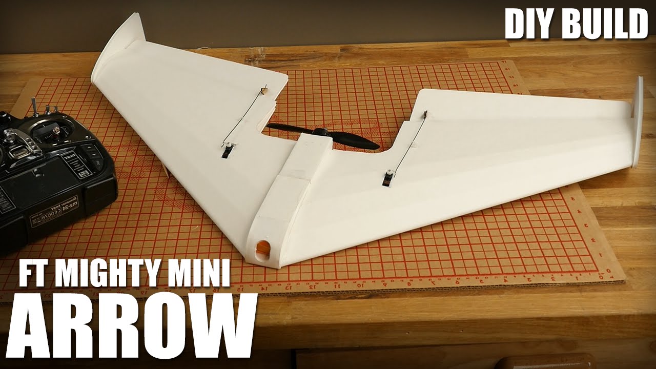
Build notes for the FT Mighty Mini Arrow
These notes are a condensed version of the FT Arrow build video.
Wings
- Do an “A” fold on the spars and glue, stop 15mm from each edge. Use a triangle to make sure the spar folds are perpendicular.
- Open the servo hole.
- Cut the bevels, double on wing and single on elevon (on the elevon side).
- Add a thin ribbon on glue on the bottom of the elevon hinge for strength, and scrape almost all of it off.
- Remove servo pocket from the wing.
- Fold the wing with the bottom on top, to curve the leading edge without crinkling the airfoil score cuts.
- Cut the side pods if you aren’t going to use a center pod.
- Glue the side pod hinges.
- Cut the main pod space on the top of the wing.
- Skewer the wing score cuts.
- Line up the spar’s servo hole onto the wing and glue onto the top side.
- Glue the airfoil’s score cuts and fold the wing so the score cuts are glued up.
- Cut the excess spar.
- Probably put the servos in now, to avoid having to make a hook later.
- Glue the leading edge, bottoms of the spar, and the end of the trailing edge, and press closed.
Joining the wings
- Tape the wings together at the bottom, glue them together in the middle, lay them down and wipe the excess glue.
- Cut the excess edge of the nose.
Center pod
- Pop out the foam tabs on the wings, where the center pod will go.
- Pop out the tabs on the center pod.
- Do an “A” fold on the bottom plate.
- Fold the little edge of the top of the center pod over (and/or add tape).
- Glue the center pod on. The backs of the wing should both be at the same height. Note that still be open/exposed, not glued down. FT leave them like that, but I like to close them up with some tape at the end so junk doesn’t get into the wing.
- Install the control horns and servos (I use epoxy for the control horns as they tend to get ripped out with just hot glue).
- Use the reflex checker foam to calibrate the wing’s reflex.
- Add a ziptie to the control rod so it doesn’t bend.
Power pod
- Install the motor onto the power pod and install the power pod. You probably don’t need to glue this, just make sure it’s tight.
- Remove the foam from the sides of the nose.
- Do a “C” fold on the back bit (and probably add some tape).
- Carefully bend the nose.
- Test fit it and glue the front part.
- Use more tape to secure the front and sides.
- Add some tape so you can pull the top open.
- Add some glue to the bottom of the top hatch so it catches and secures on close.
Winglets
- Only cut the top part of the wing, parallel to the bottom.
- Line up the reference line on the winglets and glue (the front tip of the winglet should be flush with the leading edge).
Electronics
- The rest is left as an exercise to the reader.
Last updated on November 27, 2020. For any questions/feedback, email me at hi@stavros.io.
Mini Drak build condensed instructions
Sources:
To start building:
- Nubs:
- Cut off all the nubs with a fresh blade, and sand the remainder down with a sanding block to make it flush with the rest of the foam.
- Motor:
- Cut the top left and right corner of the motor mount off, so it doesn’t conflict with the screws in the foam.
- Use only a hacksaw to open a slot in the foam for the motor mount to go through.
- Insert the mount into the slot, test it out and remove it again.
- Apply ample glue both inside the slot and on the motor mount, both on the sides and the top.
- Insert the motor mount into the slot, put a hard surface (like a hardcover book) under the foam, another hard surface at the top, add some weight or clamp and leave to cure.
- Thick spars:
- Remove the spars from the sleeves and keep the sleeves. Do not cut the spars.
- Insert the sleeves in the wings and measure them out. Mark the point in which the sleeve sticks out of the wing and cut with a dremel outdoors.
- Trim the sleeves for the main fuselage.
- Use some sandpaper wrapped around the spar to lightly scuff the body where the spars will go.
- Put the rear spar into the sleeve, to help you push the sleeve down into the foam. Make sure it’s pushed down all the way to the bottom.
- Check that the wings are straight.
- CA glue the sleeve into the body while making sure it’s flat and down all the way inside the body.
- Fill the cavity with E6000 so it seeps around the edges to hold the entire sleeve. Use lots of glue.
- Put tape over the edges so the tape doesn’t spill over either edge.
- Put the wings on something that keeps them level, so the glue doesn’t flow downhill.
- For the main body, tape the sides of the sleeve and the insides so the glue doesn’t seep in.
- Make sure the main body is level while the glue cures.
- Add spar caps and glue with E6000.
- Thin spars:
- Lightly open the channels with a hacksaw blade, so it sits exactly on the surface.
- Cut the spars longer, so you can grip the end and spin it while gluing.
- Tape around the channel so glue doesn’t spill out over the channel.
- Put glue in, turn the spar around and remove excess.
- Take the tape off ten minutes after you apply the glue, so the tape doesn’t stick.
- Elevons:
- Mark the top and bottom on the balsa.
- Cut the balsa in some way.
- Hold both elevons together and sand them together to make them identical.
- Possibly sand the balsa where it meets the body, for full articulation.
- Mount the elevons with two pieces of tape stuck to each other, overlapping, so there are two sticky sides.
- Servos:
- Possibly use larger control horns, found on Thingiverse, because reasons.
- Winglets:
- Glue the winglets completely flush with the tip of the wing.
Notes:
Make sure you use the tallest control horns possible and have loads of expo in for the roll axis (pitch is fine). Matt (because the MD is very roll sensitive as I found out to my surprise).
Last updated on November 27, 2020. For any questions/feedback, email me at hi@stavros.io.
Contents
Click on a link in the list below to go to that page:
- Battery discharge curves
- Details about my Sapphire Pro
- Electronics tips
- GRBL_ESP32 tips
- General TRMNL info
- How to properly level your 3D printer
- Info on various hardware components
- Installing BLTouch-compatible firmware onto the TwoTrees Sapphire Pro
- Notes on my TimSav
Battery discharge curves
I wanted to buy some Sony VTC6 batteries, and I was wary of fakes, so I wrote a battery discharge calculator with an associated hardware component (just a simple current and voltage sensor). I then took some measurements of my known-good batteries, and the new ones I bought.
The methodology was the following: I connected the battery to the sensor, and the sensor to a configurable load. I set the load to draw a certain amount of amps until it reached a cutoff voltage, and then to stop. I then plotted mAh drawn versus voltage, as well as amps drawn.
The batteries I connected were in various states of use, and various configurations (for various reasons, I couldn’t test single cells). The configuration, state of the battery and provenance are mentioned below.
Here are the graphs:
Genuine Sony VTC6
This is a genuine (as far as I can tell) Sony VTC6, fairly used in high amp draw situations (I use it in my plane), in a 3S configuration:

You can see that it output around 2600 mAh before I stopped it at 3V, which is quite good.
Here’s a brand new genuine VTC6, again in a 3S configuration:

This time I ran it all the way down to 2.8, and you can see it output the full 3000 mAh.
Fake Sony VTC6
This is a pretty blatantly fake “Sony VTC6”, brand new, in a 2S configuration:

The performance falls off a cliff after around 3.6V, and it only outputs 1600 mAh before it dies completely.
Trying to draw 6-7A is even more spectacular (and it gets very hot to the touch):

Notice the huge voltage sag right as the load starts drawing.
Reclaimed NKON VTC-6
I bought some reclaimed Sony VTC-6 from NKON.nl, and I tested them here, in a 2S configuration at 1.5A.
They seem to be very genuine:

Not only are they genuine, but if we compare with the graph of the brand new VTC-6 above, we see that the reclaimed NKON batteries have had zero (or very few) cycles, as they gave the same Ah at 3.3V/cell as the new ones.
If you need it, here is the raw Assault and Battery results CSV for this battery.
White CNHL 4S 4000 mAh
This is a white CNHL 4S 4000 mAh LiPo battery, slightly used:

You can see that it’s pretty decent, outputting nearly all of its nominal mAh, decently linearly, with a slightly faster drop after 3.7 V.
Last updated on December 19, 2022. For any questions/feedback, email me at hi@stavros.io.
Details about my Sapphire Pro
My Sapphire Pro runs the MKS Robin Nano 1.2 board. Details on that board (pinouts, diagrams, etc) are here:
https://github.com/makerbase-mks/MKS-Robin-Nano-V1.X/wiki/Wiring_Pinout_and_Size
TMC2209 drivers
I’ve installed TMC2209 drivers and wired all their UARTs up to the same pin, PA13, as recommended in this GitHub issue. Their addresses for X, Y, Z, and E are 0, 1, 2, and 3, respectively. It doesn’t work with Klipper, I’m only getting the error message TMC stepper_x failed to init: Unable to read tmc uart 'stepper_x' register IFCNT. Nothing I’ve tried has worked, the last resort is setting the baud rate to 19200. If you managed to make this work, please email me.
SFS 2.0 filament motion runout sensor
I’ve installed the SFS 2.0 motion runout sensor on MT_DET1 and MT_DET2. This means that the motion sensor pin is PE6, and the switch sensor is PA4. That doesn’t work either, Marlin keeps thinking the printer has run out of filament.
Someone here had the same issue as me:
https://github.com/MarlinFirmware/Marlin/issues/26916
Last updated on April 05, 2024. For any questions/feedback, email me at hi@stavros.io.
Electronics tips
This page contains various notes and tips about electronics.
Decoupling capacitors
StackOverflow has a good answer on why use decoupling capacitors in the context of a stepper driver:
There are two purposes of such capacitor:
- first it supply power for short peaks in demand, so effectively enabling the 12V power source supply much more current for short time, than it can support over long time and so the driver have more stable power and works generally better. Also it protects the driver from noise of other parts.
- the other is protect all other parts from voltage drops and noise caused by the driver. It is recomended to have capacitors as near as possible to any IC/driven circuit for this reason.
So basically - if you have good power source, you can often get away even without such capacitors. But if you power also logic from the same source, it is already better to have some capacitors on power lines where posssible. Escpecially if you expect some noise around (like having motors near or lines to motors in paralel with other lines …). Depends how much you care and how critical you see the project. Hobby project just for fun can go even without capacitors and be all good. Good industry projects have capacitors always everywhere.
I had project, where it worked even without capacitors (laser printer), but now I would place some there in any case near each driver, just to be sure. 100uF is really good capacity, enables for lot power. But if you use any other value (which you have more ready), it should not hurt too. It is not about if it would work or not, it is more about if it ensures, that it would work flawlessly even in bad conditions even under unexpected conditions and would not have “sometimes strange problems, which disapear spontaneously during debugging”.
Also note, that for improving power are good high capacity electrolytes. For preventing noise are much better ceramic (which are fast, even if they have a lot smaler capacity) and so many people put both there (like 100uF electrolyte and 100nF ceramic in paralel).
Short answer: Do as you want, it would probably work anyway. I personally would place big+small capacitors near each driver.
LDO recommendation
Asking for a recommendation for a good 3.3V LDO, someone said:
There’s a number of good parts. In the 500mA range I’d highly recommend the Holtek HT7833. If you need closer to an amp at 3.3, the Torex XC6220 is popular, but I haven’t used that one myself. Another popular part I haven’t used is the Diodes Inc. AP2112, 600mA. The Holtek has 4uA quiescent current, the other two are around 50uA. LCSC.com has all three parts.
Driving a relay
David Albert said:
When energizing a relay, you are charging a coil (inductor). To turn the relay on, you can use an NPN transistor (e.g. 2N3904) with the collector to the coil and the emitter to ground. The other side of the relay coil will go to +5V. You will need a resistor (try 1K) between your transistor base and your 3.3v control source. You will also need a diode in parallel with the coil: cathode towards +5V, anode at the junction of the transistor collector and coil. The purpose of the diode is to prevent your transistor from being destroyed when you turn off power to the coil. When you remove power from a coil, the energy stored in the coil (as a magnetic field) collapses back into the coil inducing a current flow in the coil. The voltage will climb until the current can flow (e.g. by destroying your transistor). The reverse-biased diode gives the current a path to flow so nothing gets damaged. Also, make sure your transistor is rated to carry the current needed to energize your coil (e.g. a 2N3904 is rated to deliver at most 200mA; if you need more than that, choose a transistor with a larger current rating).
The resistor between the control source (e.g. an ESP32 GPIO pin) and the base of the transistor is to limit current. Whatever goes into the base will flow directly through to the emitter (to ground)…the resistor limits that current. When current is flowing through the base-emitter junction, a much larger current will flow through the collector-emitter junction (energizing the relay coil).
There is more info on StackOverflow: Selecting a switching transistor for a 5V relay
Last updated on December 13, 2020. For any questions/feedback, email me at hi@stavros.io.
General TRMNL info
I bought a TRMNL and their docs are pretty bad, so I’ve made a list here of various info I managed to find.
- A guide for making your own TRMNL with an ESP32, it includes pinout info and how to mod the firmware. It’s in Russian, but what even are languages.
- After talking to the TRMNL team, it seems that the developer fee allows you access to the API, which lets you fetch the image that is displayed on your device. If you don’t have a device, you can buy a single virtual device for a $50 fee. This basically buys you an API key, so you can access their API.
Last updated on April 11, 2025. For any questions/feedback, email me at hi@stavros.io.
GRBL_ESP32 tips
I made a CNC that uses a custom board I designed, and which runs GRBL_ESP32. I couldn’t find the following info easily, so I’ve written it here:
- You can specify the enable pin for the drivers with the
STEPPERS_DISABLE_PINoption. This should be used like#define STEPPERS_DISABLE_PIN GPIO_NUM_2. - To invert the enable signal, you can use
#define DEFAULT_INVERT_ST_ENABLE 1. My board needed the enable signal to not be inverted (that’s what A4988/Trinamic TMC2208 drivers need), so I set it to 0. - To always keep the steppers enabled (locked) to avoid them moving, you can specify
$Stepper/IdleTime=255. That’s the maximum timeout and will always keep them enabled.
Last updated on February 15, 2021. For any questions/feedback, email me at hi@stavros.io.
How to properly level your 3D printer
I see many people on our 3D printer Facebook group ask about adhesion issues with their printer. 99% of the time, this is because they have leveled improperly, and not because of the bed material.
I have taken photos of filament when the nozzle was leveled at various heights from the bed. I greatly recommend an adjustable Z endstop, which will save you lots of time when leveling/tramming.
In this first photo, I have leveled too high (meaning the nozzle is too high compared to the bed). You can see that the filament is cylindrical, which means that it has just dropped onto the bed (or minimally touched it), leading to very poor adhesion. You can imagine that, if the filament is just dropped onto the bed, it won’t adhere well:
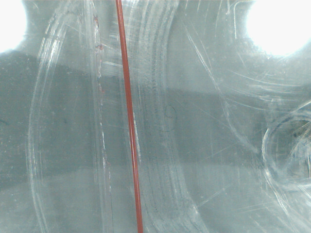
The next photo is also a bit too high. It’s not as high as the previous photo, so it has partially adhered, but there are gaps between the rows and adhesion still won’t be great:
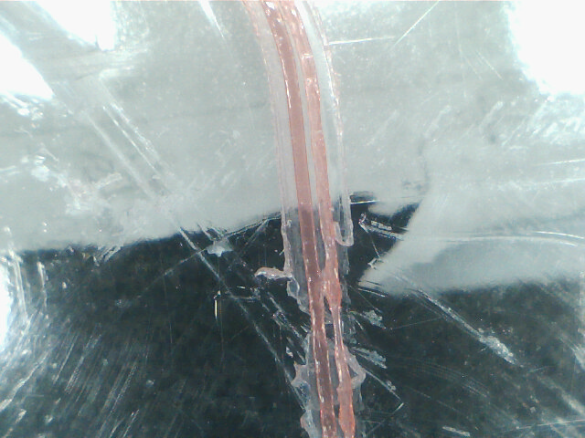
The next photo has been leveled too low. The filament is mushed against the bed, but it’s mushed too much, leading to transparent-looking rows of filament. The specific filament I’m using tends to look transparent even when leveled properly, but this is too low regardless:
For the last photo, I’ve leveled it pretty much perfectly. You can see that the rows aren’t cylindrical at all, instead they’re long strips that are touching each other properly and don’t look too transparent. If you insert a piece of paper between the bed and the nozzle, you will be able to move it with some difficulty, but it won’t move very freely.
There you have it! If your filament looks cylindrical, follow your printer’s manual to reduce the distance between bed and nozzle. If it looks transparent and missing in places completely, you need to increase the distance. If it looks mushed and has the proper color, and the rows are touching each other just so, you’re perfect and ready to print!
I hope this guide has helped you, feel free to share it with your friends.
Last updated on November 20, 2020. For any questions/feedback, email me at hi@stavros.io.
Info on various hardware components
I bought various components from AliExpress, and sometimes they lack info. I’ve added info about them here:
USB-C decoy breakouts: 5V 9V 12V 15V 20V adjustable 3A PD/QC multi-protocol decoy fast charging boost module TYPE-C USB interface
Specification:
- Supports multiple fast charging protocols
- Maximum support 3A
- TYPE-C port power supply
- Support multiple fast charging protocols: PD3.0/2.0, QC3.0/2.0, FCP, AFC
- PD/QC multi-protocol decoy 5V, 9V, 12V, 15V, 20V voltage adjustable
The manufacturer has said that this is the truth table:
| 1 | 2 | 3 | Voltage |
|---|---|---|---|
| L | L | H | 5 |
| L | L | L | 9 |
| L | H | L | 12 |
| H | H | L | 15 |
| H | L | L | 20 |
This basically seems to be the same truth table as the original USB PD decoy, except the logic levels are inverted (high becomes low and vice-versa), and SW1 in the original is M3, SW2 is M1, and SW3 is M2. Pretty convoluted, but it works.
Last updated on November 23, 2023. For any questions/feedback, email me at hi@stavros.io.
Installing BLTouch-compatible firmware onto the TwoTrees Sapphire Pro
I installed a BLTouch/3D Touch probe onto my TwoTrees Sapphire Pro, and configuring the firmware was a bit involved. The Sapphire Pro has a MKS Robin Nano v1.2 board. Here’s the process:
- Clone the Marlin repo from GitHub.
- Download the configurations.
- Check out the
2.1branch (the configurations seem to be tailored to it and I couldn’t be bothered changing). - Replace the
Configuration.handConfiguration_adv.hfiles with the ones from the configurations zip. - Uncomment the
SPRO_BLTOUCHdefine. - I also changed my dimensions to
X_BED_SIZE 230andY_BED_SIZE 225, for a more realistic bed size. - Enable Universal Bed Leveling (replace the
AUTO_BED_LEVELING_BILINEARdefine withAUTO_BED_LEVELING_UBL), as Bilinear was terrible for me. - You can also enable the Repeatability Test command with
Z_MIN_PROBE_REPEATABILITY_TEST. - Build with
pio run -e mks_robin_nano35. - Copy
.pio/build/mks_robin_nano35/Robin_nano35.binto a FAT32-formatted (important) SD card. - Insert the card into the printer and turn it on.
- Done!
Last updated on May 29, 2023. For any questions/feedback, email me at hi@stavros.io.
Notes on my TimSav
A few years ago I made a TimSav foam cutter CNC. These are my notes on it, because I keep forgetting things.
- It runs FluidNC.
M3 S200enables the spindle at 20%,M3 S0/S0disables it,M5halts it.
To generate the Gcode, I use a program called LaserWeb. I have a few notes on it:
- After you load an SVG, you need to click the leftmost button below the SVG, with the three cubes. This will select all the paths to generate movements for.
- You need to click “Create single” to create a path to mill.
- I use “Laser Cut” as the tool.
I created a small script, cnc_unwanted_moves, to remove unwanted tool off/on at each corner. I won’t share it here, as it’s too specific to my configuration, and probably useless to anyone else.
Last updated on October 02, 2023. For any questions/feedback, email me at hi@stavros.io.
Contents
Click on a link in the list below to go to that page:
Interesting projects
This is a list of interesting projects that I don’t want to forget about, in no particular order:
AI stuff
Misc
- VHS: Generates gifs of cli programs from pre-written scripts (great for documentation).
Last updated on August 07, 2023. For any questions/feedback, email me at hi@stavros.io.
Contents
Click on a link in the list below to go to that page:
Decorator that runs a function in a thread
I wrote a small decorator that will convert any function to run in a thread:
import threading

def run_threaded(fn):
    """A decorator that makes a function run in a thread."""

    def run(*k, **kw):
        t = threading.Thread(target=fn, args=k, kwargs=kw)
        t.start()
        return t

    return run
Example:
@run_threaded
def add(x, y):
    # This runs in a separate thread.
    print(x+y)

add(1+2)
That’s it!
Last updated on September 28, 2024. For any questions/feedback, email me at hi@stavros.io.
Third party AirTags research
It turns out you can buy some NRF51822 boards/tags on AliExpress (e.g. this one, but there are cheaper ones), and flash a custom firmware on them that will allow OpenHaystack integration, with the tags lasting years on a battery.
Software
- https://github.com/dchristl/macless-haystack/ - An OpenHaystack server/client pair that allows you to track your tags from any browser (this is what I use).
- https://github.com/acalatrava/openhaystack-firmware - The custom firmware (includes pre-compiled binaries).
- https://github.com/dchristl/macless-haystack/blob/main/firmware/nrf5x/README.md - Instructions on how to modify the pre-compiled firmware and flash it onto your tag (this is probably all you need).
- https://github.com/seemoo-lab/openhaystack/issues/57#issuecomment-880214651 - Some Ali boards don’t have a crystal, but a crystal makes the tag last even longer.
- https://github.com/seemoo-lab/openhaystack/issues/35#issuecomment-828338751 - More instructions for building and flashing the firmware.
General info
- https://positive.security/blog/find-you - Details about how the anti-stalking features work (or don’t).
- https://adamcatley.com/AirTag.html - A really good deep dive into the BLE transmissions of AirTags.
Last updated on November 18, 2024. For any questions/feedback, email me at hi@stavros.io.
Contents
Click on a link in the list below to go to that page:
- Black pills
- Decrypt Audible audiobooks
- Getting VoWiFi working on Xiaomi.eu
- Monero GUI syncing stuck with Ledger
- Pairing the Xbox One controller in Linux
- Resetting TP-Link Powerline plugs
- Test and format SD cards
- Various issues
Black pills
I’ve been trying to flash these Black Pills I have (STM32F401), the official STM32 flasher worked great, STM32CubeProgrammer.
Run with:
./STM32_Programmer.sh -c port=USB1 -d firmware.bin 0x08000000
dfu-util also worked, eventually, after an unspecified amount of messing around with udev rules (if it doesn’t work for you out of the box, try the rs-probe udev rules).
Useful links
- https://therealprof.github.io/blog/usb-c-pill-part1/
- https://blog.tonari.no/rust-simple-hardware-project
- https://github.com/stm32-rs/stm32f4xx-hal
This finally worked
Clone the repo: https://github.com/stm32-rs/stm32f4xx-hal/ and cd examples.
cargo objcopy --release --example delay-timer-blinky --features="stm32f401,rt" -- -O binary out.bin
dfu-util -a 0 --dfuse-address 0x08000000 -D out.bin
Last updated on December 30, 2021. For any questions/feedback, email me at hi@stavros.io.
Decrypt Audible audiobooks
To decrypt Audible audiobooks:
- Use audible-cli to get your activation bytes (run
audible quickstart). - Use Libation to manage and decrypt your audiobooks.
- Play them on whatever player you like!
Also, with ffmpeg:
ffmpeg -y -activation_bytes <bytes here> -i 'book.AAX' -codec copy 'book.m4b'
List of useful programs: https://github.com/rmcrackan/AudiobookHub.
OpenAudible is paid and expensive now.
Last updated on June 23, 2024. For any questions/feedback, email me at hi@stavros.io.
Getting VoWiFi working on Xiaomi.eu
I got a new Xiaomi phone (a Poco F4) and flashed it with Xiaomi.eu. Unfortunately, just like my Poco F3, Voice-over-WiFi wouldn’t work. I had looked before, but I couldn’t find anything, I assumed it was a problem with the phone. This time, I looked again, and found some posts hinting at it being a problem with the provisioning profile, and recommending using Qualcomm’s QPST tool to load the MBN profile.
I tried that, but the profiles weren’t there, or they wouldn’t be enabled, and in general I just couldn’t get it to work. Then, I came across a post on the Xiaomi.eu forums that ended up working for me very easily, and I’m writing it up here in case I need it again.
Enabling the profile
First, you should disable carrier checks for VoLTE and VoWiFi, just in case. You can do that by going to the dialer and entering the following number: *#*#86583#*#* (the numbers spell out “volte”, which is easier to remember). Make sure the popup says “carrier check disabled”, otherwise do it again until it does.
Then, do the same for *#*#869434#*#* (spells out “vowifi”), until that check is disabled too. Now you’ll have the appropriate menus in the settings.
To actually load the profile, you need to enter the number *#*#663368378#*#* (“modemtest”). Then, go to “MBN config loading and activing tool” shown here:
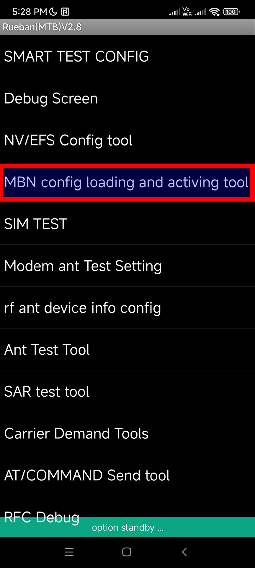
Then press “Advanced”:
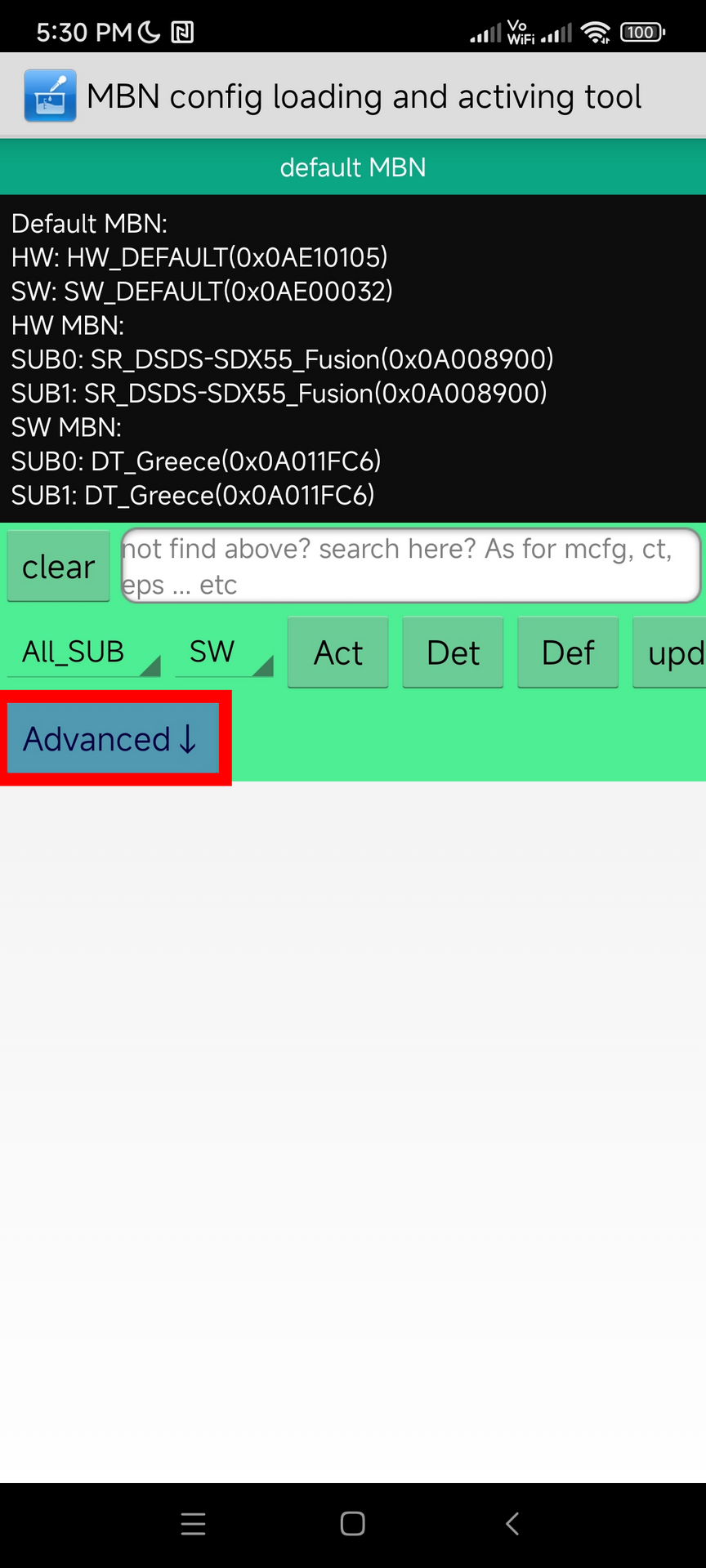
Select mbn_eea.txt (if you’re in Europe), and then press “validate”.
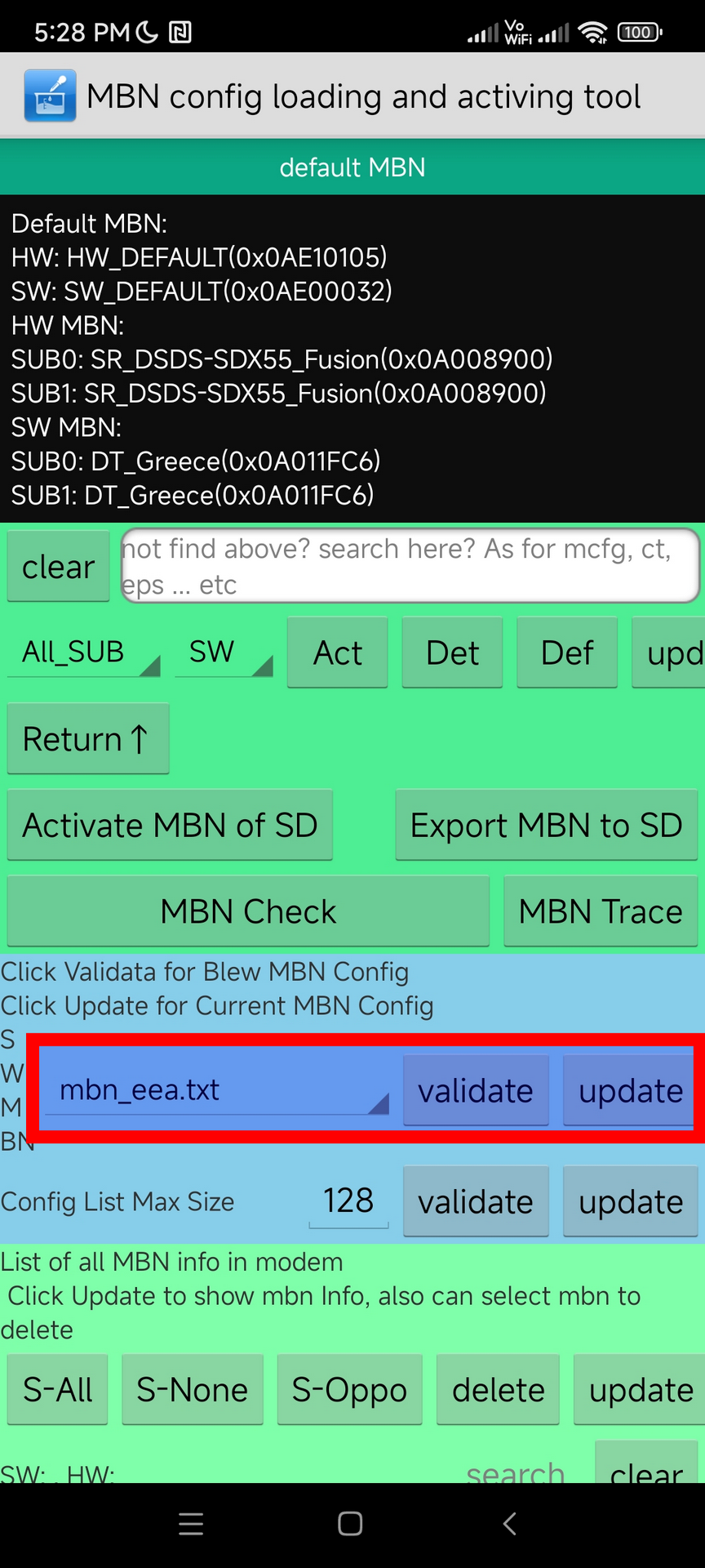
Wait for it to finish, then you should be set. Restart the phone, enable Airplane mode, enable WiFi and make a call. If it works, you’re done.
Last updated on July 23, 2022. For any questions/feedback, email me at hi@stavros.io.
Monero GUI syncing stuck with Ledger
This is about the Monero desktop GUI, but probably also applies to Monerujo.
If you’re trying to sync the blockchain with your Ledger device, you might be getting the conflicting messages of “Waiting for daemon to sync” and “Daemon is synchronized”, which then just stays there forever and doesn’t move.
You may see something like this in the log:
ERROR	wallet.wallet2	src/wallet/wallet2.cpp:3449	Error parsing blocks: Unable to send hidapi command. Error 128: Unknown error
ERROR	wallet.wallet2	src/wallet/wallet2.cpp:3512	pull_blocks failed, try_count=3
These errors are caused by the Ledger not being connected. You need to leave the Ledger connected throughout the syncing, as apparently the node needs some info from it and won’t notify you if it’s not there. It also doesn’t seem to work if you disconnect and then connect the wallet afterwards.
Letting the Ledger go to the screen saver or lock appears safe, at least with the Nano X I tried. Just leave it connected, and it’ll sync fine.
I’ve opened a suggestion on the Monero issue tracker to improve the UX of the Ledger integration in general.
Last updated on January 04, 2021. For any questions/feedback, email me at hi@stavros.io.
Pairing the Xbox One controller in Linux
Sometimes, the Xbox One controller won’t pair in Linux, instead connecting and disconnecting rapidly. To fix that:
- Install xpadneo.
- If the controller keeps connecting and disconnecting when you turn it on, make sure you upgrade to the latest firmware, that fixes that issue.
- Pair!
That should be all that’s required, your controller should now be paired.
Last updated on July 29, 2023. For any questions/feedback, email me at hi@stavros.io.
Resetting TP-Link Powerline plugs
A few years ago, I bought a pair of TP-Link Powerline plugs, and I’ve been paying for that mistake ever since (the Devolo ones have given me zero trouble). They constantly desynchronize and need to be paired again.
This is the process, so I don’t forget:
- Press the button for around 7 seconds, until the lights all go dark and light up again. Don’t do this while the pairing light is blinking, it doesn’t seem to work.
- Press the pairing button once.
- Repeat this process on the second plug.
- They should pair now.
- Get Devolo plugs.
Last updated on May 25, 2023. For any questions/feedback, email me at hi@stavros.io.
Test and format SD cards
I wrote a short bash script that tests SD cards with F3 to see if they’re fake, deletes everything on them, creates a new partition table and one exFAT partition on them.
Here it is:
#!/usr/bin/env bash

set -euox pipefail

sudo umount --force "$1"1 || true
sudo f3probe --destructive --time-ops "$1"
sudo parted --script "$1" "mklabel msdos" "mkpart primary ext4 0% 100%"
sleep 1
sudo mkfs.exfat -n Stavros "$1"1
eject "$1"
Save it as formatsd.sh and run it as ./formatsd.sh /dev/sdX.
Last updated on August 18, 2021. For any questions/feedback, email me at hi@stavros.io.
Various issues
Tailscale keeps breaking my Docker DNS resolution
I run Tailscale on my PC and Docker keeps being unable to resolve DNS hostnames. I try to build a container that upgrades Debian and keep getting Temporary failure resolving 'deb.debian.org', for example.
This comment on GitHub had the solution:
# Run this on the host.
sudo tailscale set --stateful-filtering=false

* * *

<p style="font-size:80%; font-style: italic">
Last updated on October 20, 2025. For any questions/feedback,
email me at <a href="mailto:hi@stavros.io">hi@stavros.io</a>.
</p>
Contents
Click on a link in the list below to go to that page:
Cloning cards/fobs with a Proxmark3
Cloning a Paxton fob
Basically, follow this guide:
https://badcfe.org/how-to-paxton-with-proxmark/
I managed to read my fob with:
lf hitag read --ht2 -k BDF5E846
If you’re getting “Password failed!” or nothing back, move the fob around the 125KHz antenna (the top one), it should eventually work.
Afterwards, convert the fob pages to an EM4100 ID, and flash the ID to a T5577, emulating an EM4100 chip:
lf em 410x clone --id <your hex id>
Read it back to make sure:
lf em 410x reader
You should be done, but I haven’t tested it as I don’t have a Paxton reader handy.
Cloning MiFare cards
See Cloning a Mifare Classic 1K.
Working with T5577
Always remember to run lf t55xx det every time you change configuration (not content) to make sure your card is detected properly.
Card cloner password
I have an AliExpress cloner which clones LF cards. Unfortunately, whenever it clones a card, it sets the password bit on it. This makes the card not respond to writes/wipes without the password (it just keeps having the same data, no matter what you write).
To remove it with the Proxmark3, run:
lf t55 wipe -p 51243648
Cloning T5577 cards
Read the card with:
lf em 410x reader
Write with:
lf em 410x clone --id <the ID from before>
Related reading
- Iceman’s Proxmark3 firmware (use this one)
- How to copy Paxton fobs using an RFIDler
- How to copy, read and write Paxton fobs and cards with a Proxmark
Last updated on January 14, 2025. For any questions/feedback, email me at hi@stavros.io.
Flipper Zero notes
Useful links
- CAME protocol brute forcer.
- A more generic sub-Ghz brute forcer
- How the sub-Ghz remote app works
- How to store 2 to 3 different EM41xx on a single T5577 (this never worked for me)
- Universal Radio Hacker
- Flipper Maker
- Awesome Flipper Zero
- KeeLoq datasheet
- Beginning NFC, a pretty comprehensive book on NFC
Videos
- This EEVblog video has very useful information on how IR protocols work: EEVblog #506 - IR Remote Control Arduino Protocol Tutorial
- Samy Kamkar’s DEF CON 23 video Drive it like you Hacked it is a great intro to how non-rolling-code garage openers (and other old bit-shift receivers) work.
- Excellent deep-dive into rolling code 433 MHz protocols
- Lots of detail about KeeLoq, and some attacks.
Last updated on January 21, 2025. For any questions/feedback, email me at hi@stavros.io.
MIFARE cracking info
From kweks on HN:
There are multiple ways to crack MIFARE - depending on the actual chipset version / manufacturer. For Mifare Classic: - Nested (Uses one known key to crack others) - darkside (Derives a key with no others. Slower, results are typically handed off to the nested attack to calculate remaining keys..)
For newer versions of the Mifare Classic with better PRNGs - “Hardened” cards: HardNested. Needs one known key.
For cards that provide a static nonce (to try to evade cracking, ie FUDAN) - Static Nested.
For the latest generation FUDAN: Static Encrypted HardNested.
Note, for the nested attacks - if you don’t have a known key, these can be sniffed from the access control reader, and then cracked (MFKey32/64).
Flipper supports the MFKey32 attacks, and limited nested. You may bump into limits of your Proxmark clone with hardnested cracking - it’s memory intensive, and most of the Proxmark Easy clones have reduced RAM.
There’s actually an auto_crack LUA script on proxmark ( Use this fork: https://github.com/RfidResearchGroup/proxmark3 ) which will take most of the hassle out of cracking.
Cracking requires very, very precise timing: In a nutshell, you’re trying to predict nonces / PRNG values, by sending very precicesly timed requests, and then later cracking those results.
The Flipper has limited CPU power - its main “attack vector” against MIFARE is a very large keylist / dictionary of common MIFARE keys. It’s slow and dumb, but it works for most cases. It can also do limited cracking, depending on the type required.
The Proxmark is built around an FPGA, and can crack much, much more efficiently.
Last updated on September 20, 2024. For any questions/feedback, email me at hi@stavros.io.